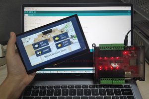
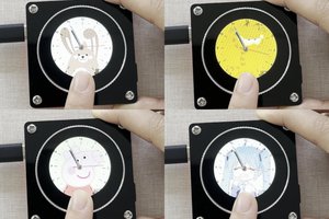
In this article, I'm going to make a digital combination lock, using Squareline_studio and MaTouch ESP32-S3 Rotary IPS Display with Touch 2.
To make the experience fit your profile, pick a username and tell us what interests you.
We found and based on your interests.
video_20231013_153116.mp4the video of resultMPEG-4 Video - 5.96 MB - 12/13/2023 at 05:42 |
|
As shown in the video of result, the MaTouch ESP32-S3 Rotary IPS Display with Touch 2.1“ ST7701 also has a WiFi function, which can get NTP and display the actual time in the center of the screen.
Turn the encoder to control the value change, press the screen for password confirmation, when the correct password is entered, the LED lights up and the second screen shows up。
The MaTouch ESP32 S3 2.1 Rotary TFT with Touch is not compatible with the TFT_eSPI library, so I use the GFX_Library_of_Arduino library instead of the driver.
#include <TFT_eSPI.h>
TFT_eSPI tft = TFT_eSPI(screenWidth, screenHeight); /* TFT instance */
tft.startWrite();
tft.setAddrWindow( area->x1, area->y1, w, h );
tft.pushColors( ( uint16_t * )&color_p->full, w * h, true );
tft.endWrite();
tft.begin(); /* TFT init */
tft.setRotation( 3 ); /* Landscape orientation, flipped */
Arduino_ESP32RGBPanel *bus = new Arduino_ESP32RGBPanel(
1 /* CS */, 46 /* SCK */, 0 /* SDA */,
2 /* DE */, 42 /* VSYNC */, 3 /* HSYNC */, 45 /* PCLK */,
11 /* R0 */, 15 /* R1 */, 12 /* R2 */, 16 /* R3 */, 21 /* R4 */,
39 /* G0/P22 */, 7 /* G1/P23 */, 47 /* G2/P24 */, 8 /* G3/P25 */, 48 /* G4/P26 */, 9 /* G5 */,
4 /* B0 */, 41 /* B1 */, 5 /* B2 */, 40 /* B3 */, 6 /* B4 */
);
// Uncomment for 2.1" round display
Arduino_ST7701_RGBPanel *gfx = new Arduino_ST7701_RGBPanel(
bus, GFX_NOT_DEFINED /* RST */, 0 /* rotation */,
false /* IPS */, 480 /* width */, 480 /* height */,
st7701_type5_init_operations, sizeof(st7701_type5_init_operations),
true /* BGR */,
10 /* hsync_front_porch */, 8 /* hsync_pulse_width */, 50 /* hsync_back_porch */,
10 /* vsync_front_porch */, 8 /* vsync_pulse_width */, 20 /* vsync_back_porch */);
void my_touchpad_read( lv_indev_drv_t * indev_driver, lv_indev_data_t * data )
{
int touchX = 0, touchY = 0;
if (read_touch(&touchX, &touchY) == 1)
{
data->state = LV_INDEV_STATE_PR;
data->point.x = (uint16_t)touchX;
data->point.y = (uint16_t)touchY;
}
else
{
data->state = LV_INDEV_STATE_REL;
}
}
To establish a connection between the rotary encoder values and the values of the semi-circle and the labels, some intermediate processing is required.
attachInterrupt(ENCODER_CLK, encoder_irq, CHANGE);
void encoder_irq()
{
State = digitalRead(ENCODER_CLK);
if (State != old_State)
{
if (digitalRead(ENCODER_DT) == State)
{
counter++;
}
else
{
counter--;
}
}
old_State = State; // the first position was changed
}
void cal_encoder()
{
USBSerial.print("Position: ");
USBSerial.println(counter);
target_count = (counter % 20) / 2;
if (target_count < 0)
{
target_count = (counter % 20) / 2 + 10;
}
if (target_count > arc_coun)
arc_coun++;
else if (target_count < arc_coun)
arc_coun--;
USBSerial.print("arc_Position: ");
USBSerial.println(arc_coun);
}
lv_arc_set_value(ui_Arc1, (int)arc_coun);
if (label_flag == 1)
{
_ui_arc_set_text_value(ui_Label1, ui_Arc1, "", "");
if (arc_coun == 2)
{
if (digitalRead(BUTTON_PIN) == 0)
{
USBSerial.println("Button Press");
while (digitalRead(BUTTON_PIN) == 0)
{
delay(50);
}
label_flag = 2;
}
}
}
if (label_flag == 2)
{
_ui_arc_set_text_value(ui_Label2, ui_Arc1, "", "");
if (arc_coun == 4)
{
if (digitalRead(BUTTON_PIN) == 0)
{
USBSerial.println("Button Press");
while (digitalRead(BUTTON_PIN) == 0)
{
delay(50);
}
label_flag = 3;
}
}
}
if (label_flag == 3)
{
_ui_arc_set_text_value(ui_Label3, ui_Arc1, "", "");
if (arc_coun == 6)
{
if (digitalRead(BUTTON_PIN) == 0)
{
USBSerial.println("Button Press");
while (digitalRead(BUTTON_PIN) == 0)
{
delay(50);
}
label_flag = 4;
}
}
}
if (label_flag == 4)
{
_ui_arc_set_text_value(ui_Label4, ui_Arc1, "", "");
if (arc_coun == 8)
{
if (digitalRead(BUTTON_PIN) == 0)
{
USBSerial.println("Button Press");
while (digitalRead(BUTTON_PIN)...
Read more »
Choose the Arduino and enter in parameters. According to the features of MaTouch ESP32 S3 2.1 Rotary TFT with Touch, the resolution is 480*480, the shape is a circle, and the color depth is 16-bit.
Add the images and fonts you like to assets, and then it allows you to select them and widget components to design the scenes. After, clicking the widget of the list on the Hierarchy panel, you can modify the parameters of the select widget on the Inspector panel, all is determined by your preference.
Here, I'd suggest selecting some photos that hold cherished memories for both parties.You also can place some words you want to say to other person on the second screen, so they can discover them upon unlocking.
connect J2 to LED: 3V3 to V and TX to G
Yes, just that. It's super easy.
The rotary encoder and its pressable operation are perfect for making a combination lock. The rotary encoder controls the value change and the pressable operation is used to confirm the code.
Create an account to leave a comment. Already have an account? Log In.
Become a member to follow this project and never miss any updates