 AIB
AIBDescription
This uninterruptible power supply (UPS) can be powered using an external 12V DC power supply. It supplies 12V/48W (4A) and can briefly deliver up to 5A (60W). It can be used to protect small electronic equipments such as small servers (SBC based) or routers.

Overview
The UPS is enclosed in a 3D printed case. All power connectors are XT30 (male for input, female for output). A switcher circuit switches between external 12V DC and internal 12V DC. A down-converter converts the battery pack output voltage (typically 14.8V) down to 12V. A 4S charging circuit charges the battery pack when external 12V DC is available. It also monitors the battery's temperature and voltage: it stops charging if the battery's temperature gets too high and it shuts down the down-converter if the battery's voltage is too low. The charging circuit requires at least 17V to operate, therefore a boost-converter is used to convert the external 12V DC voltage to 20.1V DC. A thermal monitoring circuit is used to turn on the cooling fan if the down-converter gets too hot. All circuit boards can be steadily mounted in the PLA enclosure.


Switcher
The switcher module is built around the LTC4418 IC. This IC is used to connect an output to one of two input power sources, P1 and P2. P1 has a higher priority than P2. In our case, P1 is the external 12V DC power supply and P2 is the power source connected to the battery (through a 12V down-converter).

The IC constantly checks the validity of each power source Pi: UVi < Pi <OVi, where UVi and OVi represent respectively the undervoltage limit and the overvoltage limit for power source i. Each source's validity is indicated by their respective LEDs (D1 and D2). These can be set through a precise choice of resistors. The undervoltage limit for P2 has been chosen as low as 4.85V to avoid power interruption when transitioning from P1 to P2 under heavy load. The large capacitor at the switcher's output ensures voltage stability during the transition. This design is much more efficient than the typical use of diodes, as it avoids the inherent diode voltage drop and resistance under load. A Python computation file for resistor values is provided to explain the resistors choice.
Battery pack
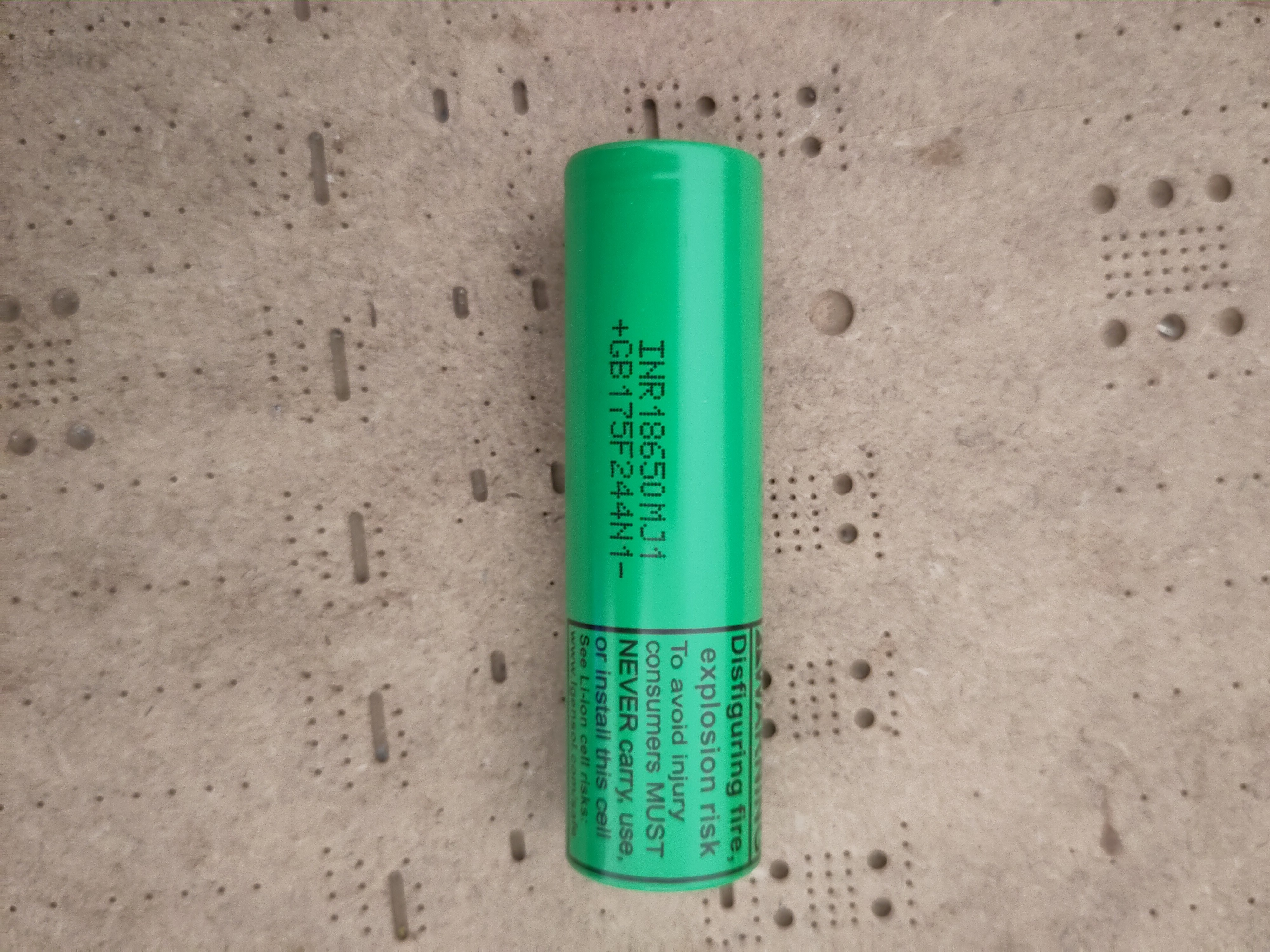
The battery is a li-ion 4S/2P pack of 18650 cells. Each cell's voltage was carefully measured and balanced to be fitted with another cell in parallel. Each cell has a capacity of 3500 mAh and a maximum output current of 10A.
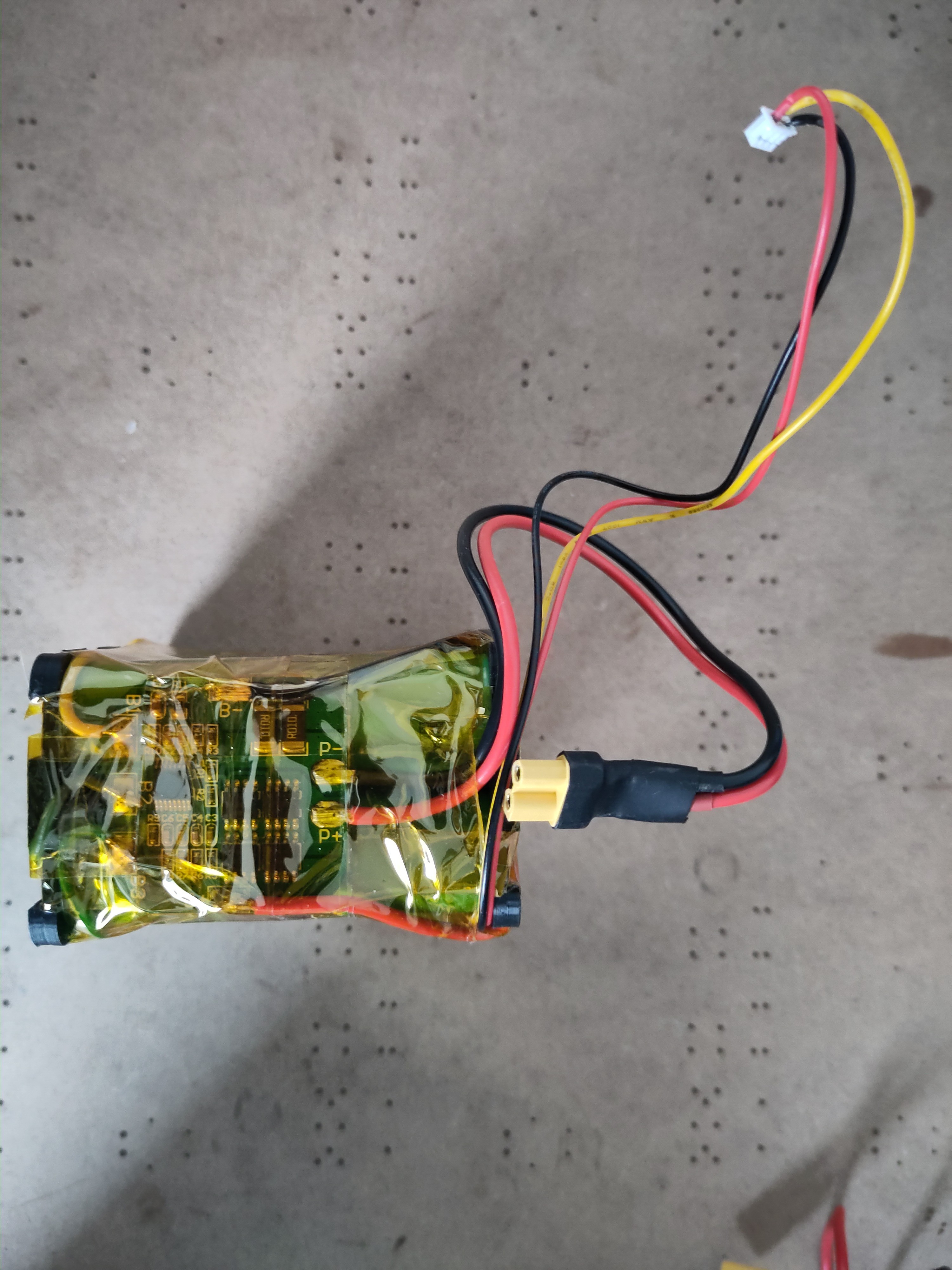
The four parallel units were then assembled in series to form the final pack, using a 3D printed spacer. A 4S 10A BMS is used to balance the charge accross the different cells. A LMT85 temperature sensor is used to monitor the battery's temperature during charging. The sensor is connected to the charger module and is inserted between two cells with some thermal paste. Detailed operation of this temperature sensor is explained in the charger section.

Battery charger and up-converter
The battery charger module is built around a MP26124 IC. The charging current has been limited to 1.35A through a resistor choice to avoid excessive heat during charging and to prolong the battery's life. An inverted comparator with hysterisis (built using a LM393) is used to monitor the temperature sensor's voltage. The LMT85 has a negative slope near-linear ouput voltage. The comparator's output is low (enabling the charging IC) as long as the temperature sensor's output voltage Vtemp is higher than a low threshold Vlow. If the temperature gets too high, Vtemp decreases. The comparator's output gets high and shuts off charging....
Read more »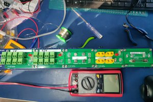
 Enki
Enki
 Real Solar Cars
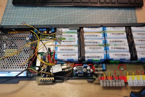

 Open Green Energy