 Collin Matthews
Note - Documentation In Progress
Interested in purchasing some of the boards seen here? Check out my Tindie.
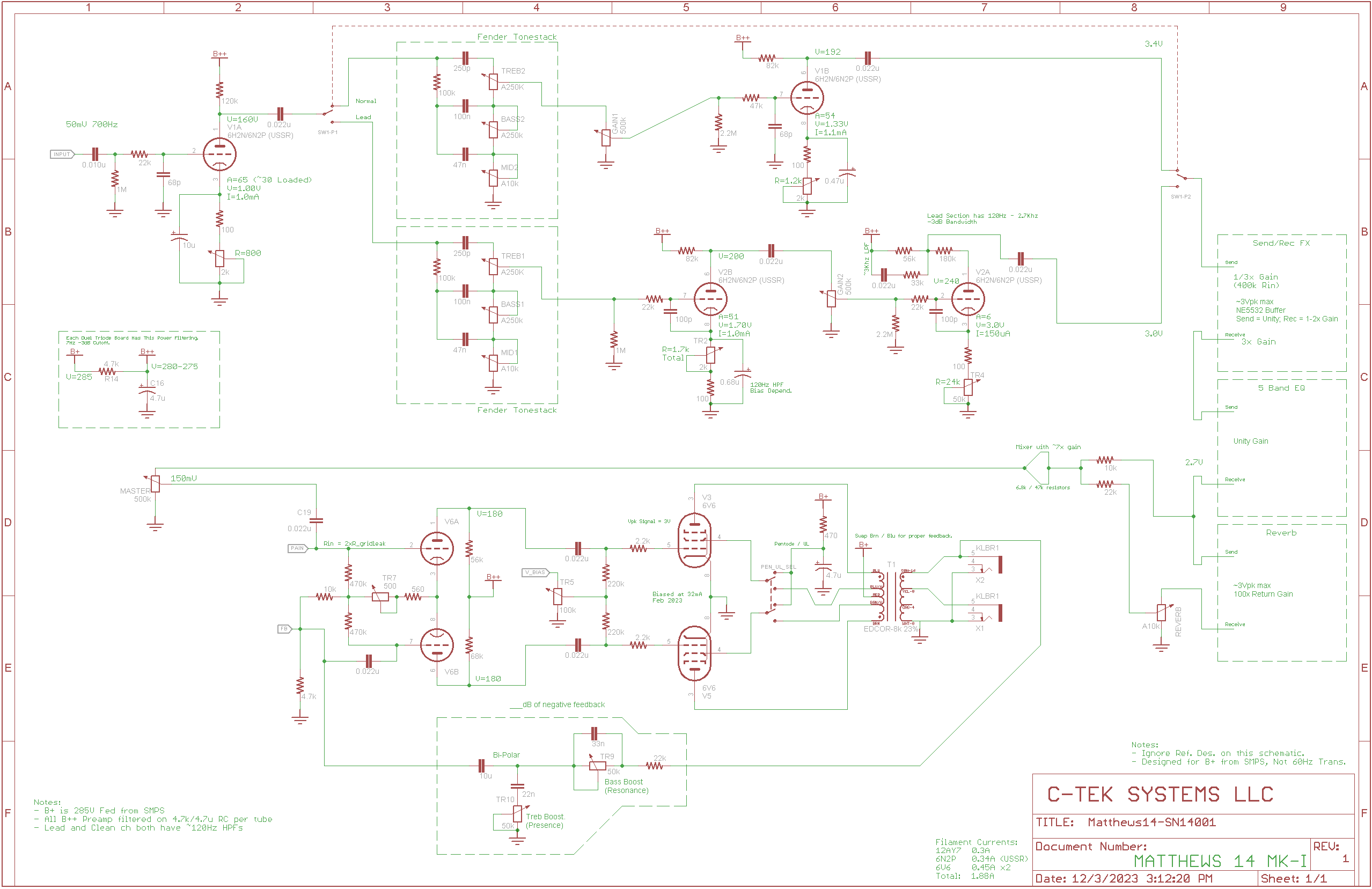
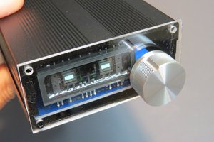
This amplifier went through multiple revisions over ~3 years. While the clean sound has always stayed the same. The lead channel was lacking, as well as a real chassis. Below is the circuit I ended up with after that time. People often ask what amp it is modeled after, the truth is none. It was made from the ground up, just designing using 70 year old data sheets for tubes, and understanding how to get a good distortion from a tube for the lead channel.
I will say the tone stacks are fender (as are ~90% of amps on the market), other designs were tried but fender is the best from component maximization and tone adjustment. Also anyone familiar with Mesa Boogie may find the 5 band master EQ familiar, I liked the idea of using early tone adjustment to more effect distortion and drive, with a later equalizer to adjust for overall sound and cabinet matching.
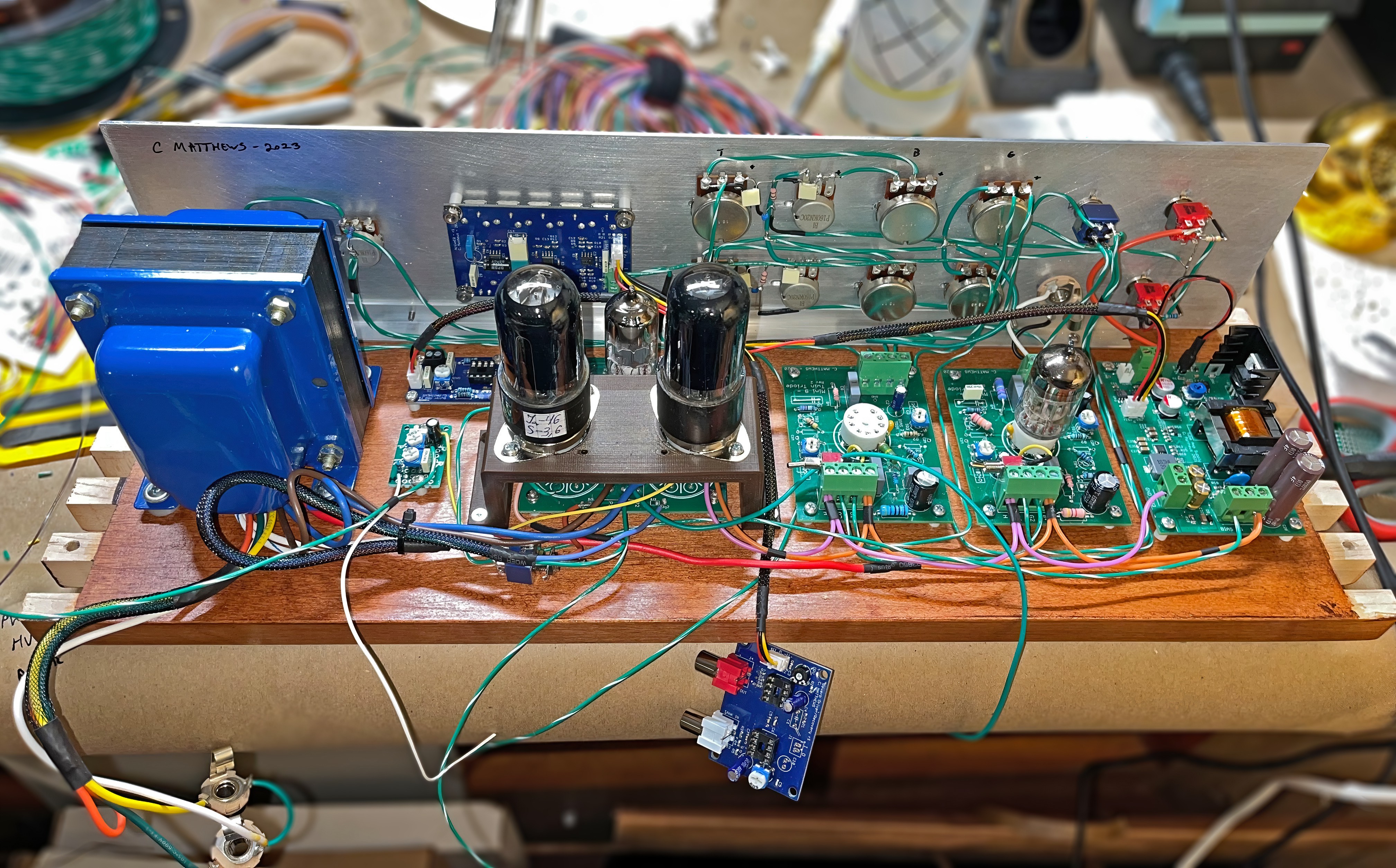
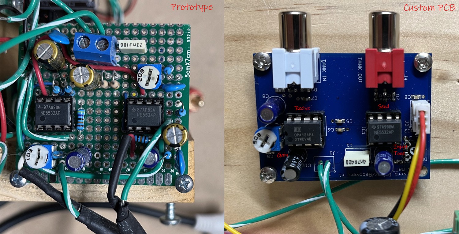
For the internals, I again used the prototype tube boards I designed in 2018. This made adjusting components easier, but in the long term, it adds a reliability risk that I would like to fix by making a single PCB or using solder instead of screw terminals.
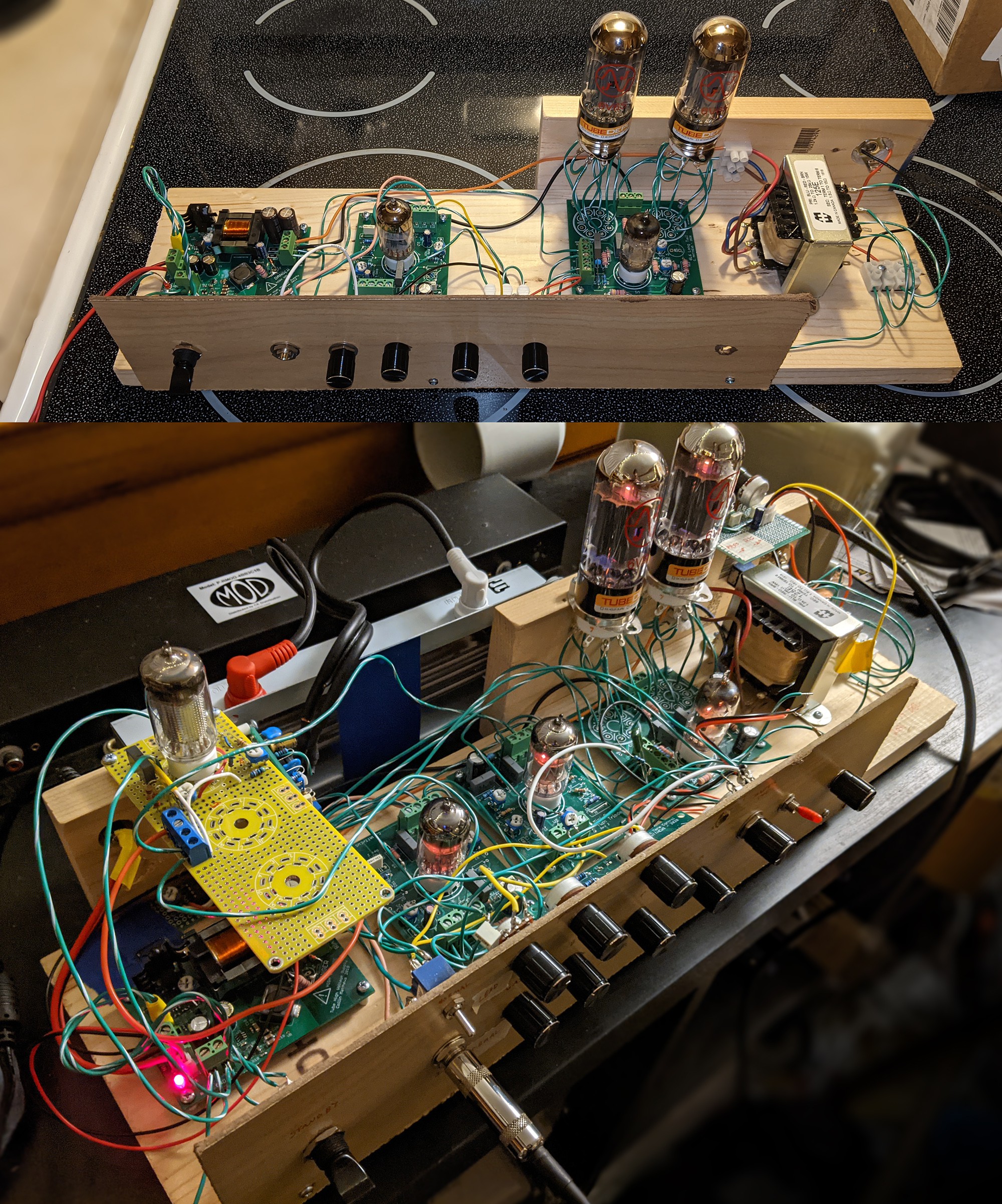
It may also be worth noting, it did not start off this nice. Here is the original test platform. I find a good pine board and a piece of hardboard (wall panel) makes a nice face. You may also notice the output transformer changed, I found even with negative feedback, the cheap Hammond universal output transformer had a less then ideal sound quality. Moving to a larger HiFi transformer (Edcor CXPP25-8K/23%) with ultra-linear taps really changed the tone.
I also went through multiple revisions for the lead channel, testing out different bias configurations and even a high gain EL86 type pentode. In the end I stuck with a single twin triode tube (Soviet 12AX7), with a cold and hot bias, and some tone shaping networks on the input and output to cut the bass and high end.
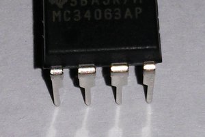
The only constant throughout development has been the SMPS for all the voltage control, although that went though its own design cycles and will eventually have its own page here.
As built schematics:
See the soon to exist project log for more in-depth details.


 Arno
Arno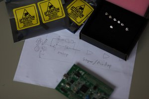
 kodera2t