Close
0%
0%

MC34063 based Bench power supply

Title says it all. It will also include digital control
Similar projects worth following
Dual channel power supply based on MC34063 running on independent windings of a microwave transformer. It will contain digital control of the voltage. More to come soon.

I am in need of a power supply for some projects I want to do and did not want to convert an ATX supply. I was inspired by The big one's power supply. Only with less ambitious goals, aim for only 2 channels.

  • 3 × MC34063 Power Management ICs / Switching Regulators and Controllers

  • Holding patterns

    NDX580005/05/2015 at 05:06 1 comment

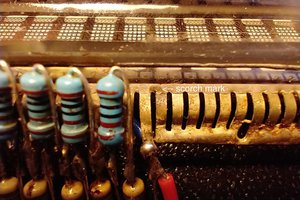
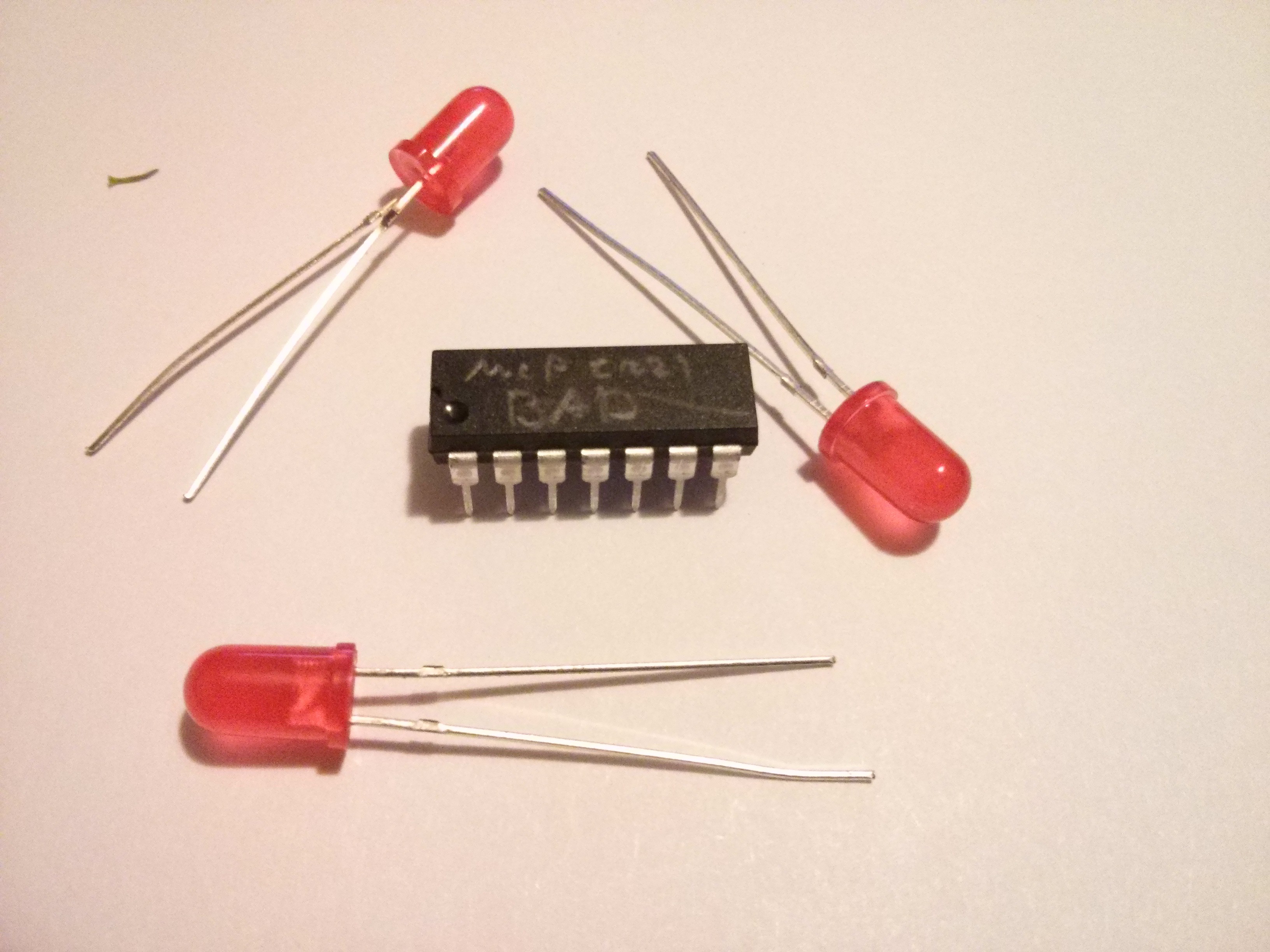
    This project is on hold as I blew my monthly budget for three other projects i want to work on. The first causalities are shown below. (IDK how those leds died, they weren't connected to anything)

    (IF you know what that chip is, rest assured, 1 more is on the way.)

    Next log for the bench power supply project will be when the parts arrive or when i finally decide on a schematic for it.

  • Amplifying our differences

    NDX580003/23/2015 at 01:03 0 comments

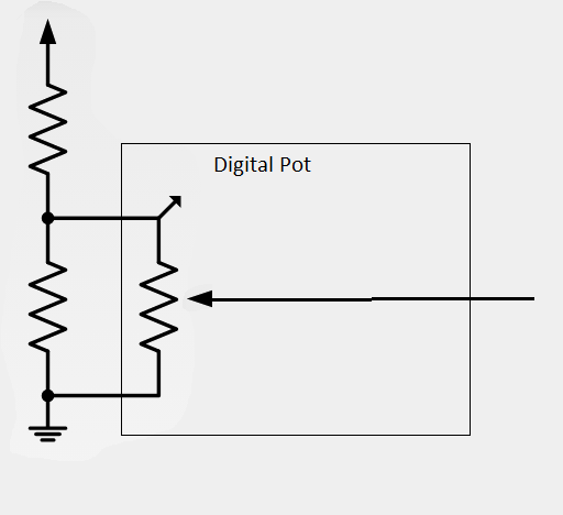
    I have decided to make another design change, but i did find a solution to a problem. The digital pots that i have chosen have a limitation. Maxim's DS3904U can't have more than .3v above V+ on the resistor or wiper of the chip. The initial solution was to use a simple voltage divider, like shown below.

    The only problem is that would i would not have the full voltage range i wanted. The lowest voltage i would be able to achieve would have been six volts.
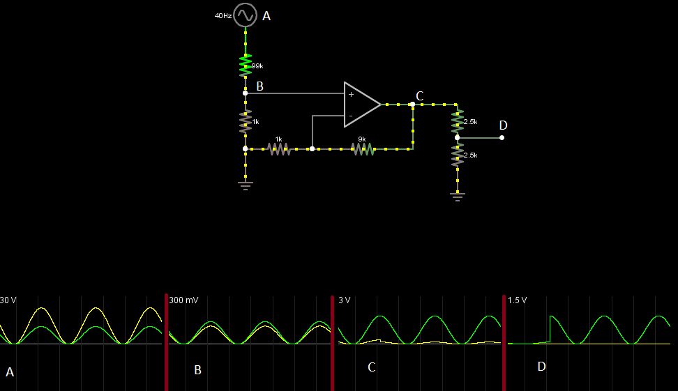
    The solution was to use a voltage divider to divide the 30 volts down to 300 mV or so. Then use an op amp to bring up the v to about 3 volts. Then use that to drive the digital op amp. As shown below in the simulator.

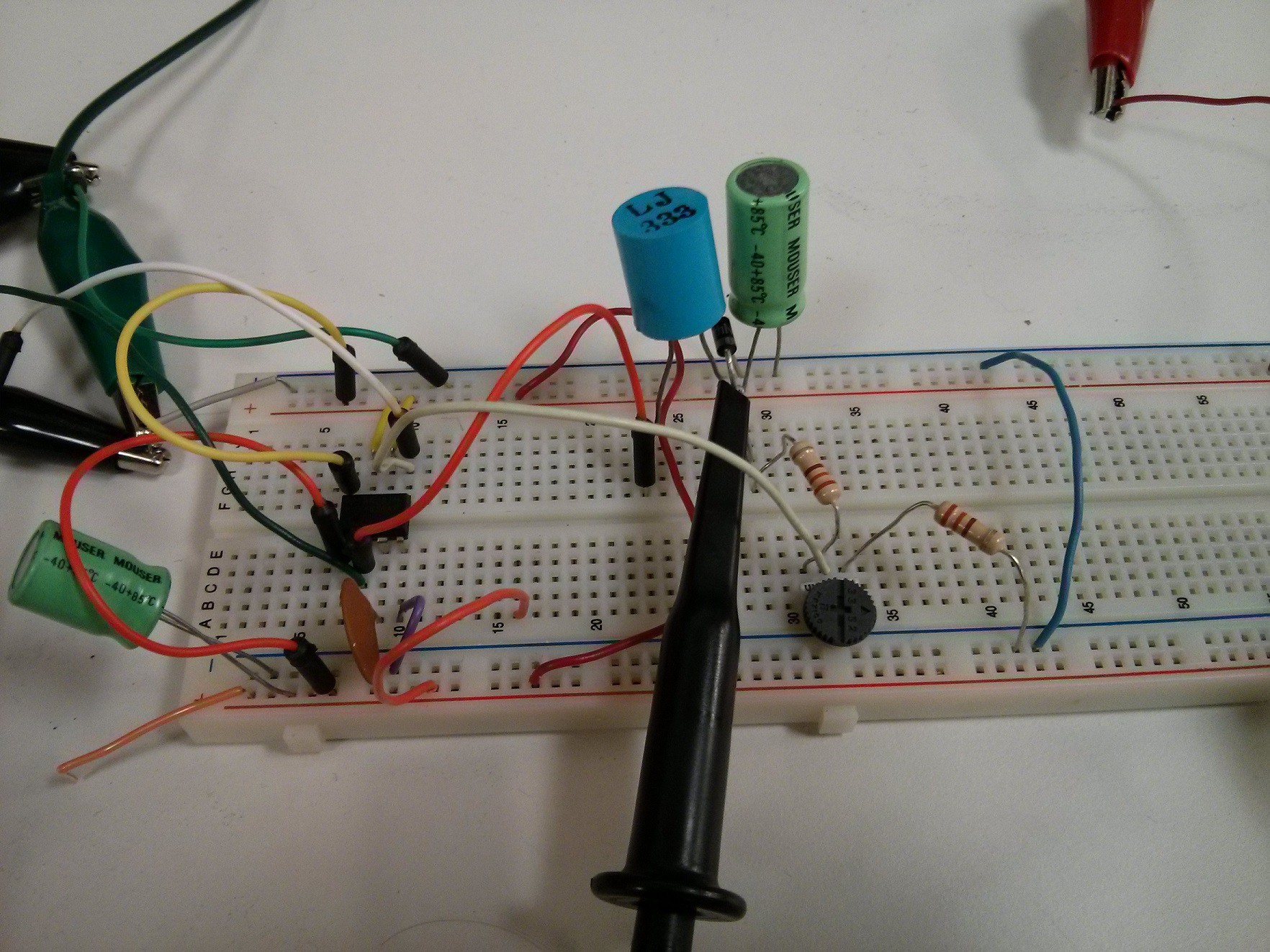
    In reality, it looked like this. I used pots since I know theory doesn't always become reality. That meter on the upper right shows the voltage going into the divider. 1st pot on the right was the voltage divider, and the other one was the feedback for the op amp. The op amp later drives that thumb wheel pot in the middle.
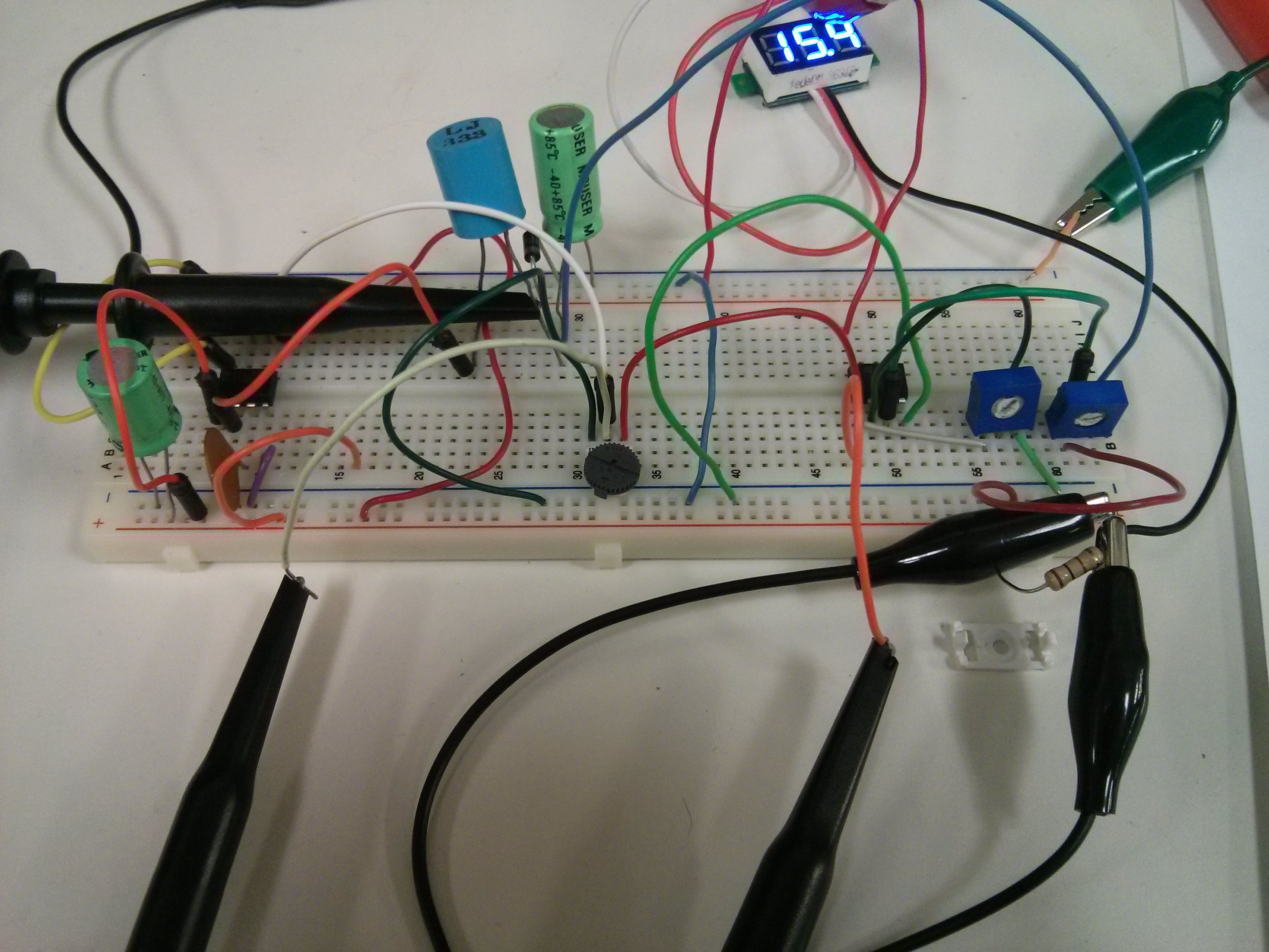
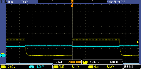
    Unfortunately, i forgot to take scope snapshots of the circuit in action. However, the proof of concept did work. Yet, i noticed that near the ends of the pot, the change in the output voltage change dramatically. It did not act linearly.

    I'll poke around to fix that later and take scope snapshots of it in action.

  • Getting on with MC34063

    NDX580003/05/2015 at 05:52 0 comments

    Even though i thought of a different way to control the chip involving a digital Potentiometer ( going to prototype later), I found that that you can control the chip by feeding the feed back pin directly.

    The set up follows the provided buck schematic from the datasheet except the feed back pin is hooked up directly to a signal generator. ( I forget to take a picture of the setup.)

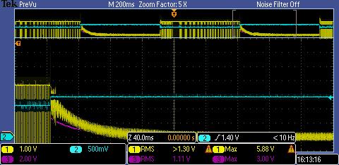
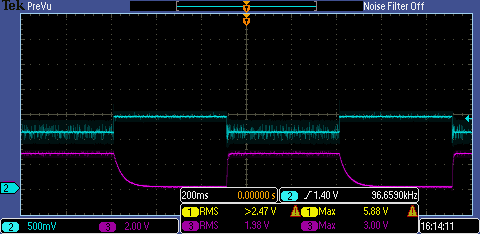
    I feed the chip with a square wave with a high voltage of 1.3 an a low voltage of 1.2. In other words , a .05 volt square wave with a dc offset of 1.25 volts.

    Blue is the Signal generator

    Yellow is the output of the chip

    (Note: Chip only, with a 200 Pf cap, No inductor )

    Same channel setup , purple is voltage output in buck mode. Now the chip behaves a bit different. The decay curves after the feedback goes high remind me of discharge curve of a capacitor. I don't have any clue to why the chip does this.

    (Note: Now includes inductor)

    Here's another picture, only with the signal gen and the output.


    When I finished, I decided to set the chip up exactly like in the example in the datasheet, with some components substituted, namely the inductor.

    (NOTE: I did not use a load resistor.)

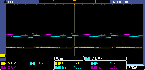
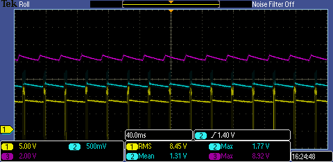
    I took two snapshots of it in action.

    This surprised me in that the chip adjusted its operating frequency on the fly. I don't think it will cause me any trouble with the inductor I want to use except at the lower output voltages.( The faster, the better. Its ~20 uH inductor from a decent quality ATX power supply.)

  • Launch !

    NDX580003/02/2015 at 00:18 1 comment

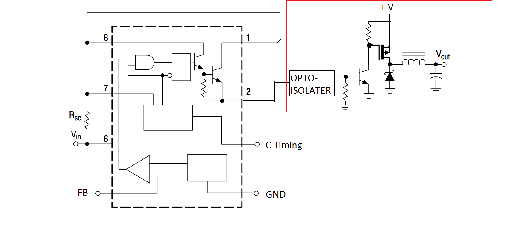
    I'm basically going to use the example layout provided by the chip's datasheet for buck converters with some modifications.


    The area highlighted in red will be controlled through an opto-isolater from the MC34063. I will be using a combination of a NPN transistor to turn on the P-Fet as fast as possible with a low resistance pull up resistor for quick turnoff.

    The main reason why i want this kind of isolation is so i can tie the channels together in series or have a +V to GND to -V rails.

    Later this week, I will be testing if directly applying a voltage to the feed back pin will allow me to manipulate the output. Those results (among others) will determine if i continue with these project.

    Any feedback will be greatly appreciated.

    PS. Can someone suggest an opto-isolater that can work above 200 KHz ? I'm not sure on what to look for in a opto-isolater.

View all 4 project logs

Enjoy this project?

Share

Discussions

Similar Projects

Does this project spark your interest?

Become a member to follow this project and never miss any updates