 Bharbour
One of the goals on this project was to make as little modification to the original load box as possible. The mechanical construction of the unit helped with this. The top cover of the box is just a flat sheet of aluminum. This made a convenient place to put my electronics as sort of a backpack. Most of the connections to the load box are via terminals on the back of the unit. The only connections into the internals of the load box are the switched AC power source to feed the control hardware. A connector is added into the AC wiring on the load box to make it easy to remove the backpack.
A manual came with this unit, but it was for a different model that had much higher current and power handling capabilities. The schematic provided a rough idea of how the unit is wired, but there are significant differences between this load box and the manual. The manual showed that the control voltage range was 0V to +6V, which is a pretty convenient range to work with modern analog components. I verified this with a boat anchor power supply, a precision current sense shunt resistor, a good voltmeter, and a DC voltage calibrator. Taking a dozen measurements manually, the transfer function between control voltage and the current sink was checked and turned out to be fairly linear.
This load box will handle up to 50 volt inputs and sink up to 15 amps, with a maximum power level of 150Watts. It is also small enough to not take up an enormous amount of storage space when not in use.
One of the issues with test equipment is the relationship of the test connections with the safety ground on the AC plug. Some instruments like scopes generally have the input grounds tied directly to the safety ground. Computers generally do too. Power supplies, and multimeters generally float the external connections with respect to the safety ground. This load box has it's input floating with respect to the safety ground. This is important because it is possible to have the safety ground become an unexpected short circuit, and with power supplies and load boxes, the currents may be large. I have seen a few destroyed USB ports on laptops and PCs as a result of this issue. I really wanted to preserve this isolation with my load box control stuff. Getting the grounds right on this project proved to be one of the more difficult parts.
Looking at the schematic in the manual for the larger load box, it indicated that the current was sensed with a 2 milliOhm resistor. This value would work well with the INA230 power monitor chip and I could re-use the signal from the internal current sense resistor. The INA230 has a maximum input voltage of 36 volts and allows using the sense resistor in the ground path so the current sense voltage would be close to ground. A voltage divider was placed in front of the voltage input of the INA230 to keep it's input voltage within the legal range while the load box could see up to 50V. Using these ideas, I designed the analog interface board. Testing this idea showed that the current sense resistors in the load box that I have are actually 33 milliOhms. This does not work with the INA230.
The signal ground in the load box is not the - power input binding post. Signal ground in the load box is on the far side of the current sense resistor from the - power input binding post, so the - input binding post sits below the load box signal ground by the current sense voltage. Control voltage to set the load current remotely requires a stable connection to the signal ground. To avoid problems between the control board analog ground and the load box signal ground, I decided to add my own current sense resistors on the + side of the input power. The INA230 will work with this configuration too. This choice limited the maximum input voltage to the load box to +36V, but for the work that I do, that is not a problem. A new set of input binding posts got added to the control back pack, with a 5 milliOhm sense resistor. The new - input binding...
Read more »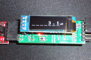
 Alex Fatiuk
 The Big One
 Jasper Sikken
 Bud Bennett