HaD Prize 2015 Questions:
What problem does this solve? Just about every hacker in the world needs a good power source. While re-commissioning an ATX supply is a rite of passage, these supplies are somewhat limited in what they can do. They tend to only have 4 fixed voltages (12, 5, 3.3, and -12); futhermore, you need to use multimeters to determine actual voltage / current output. There is no current limiting (if you short the rails the supply will turn off, but it will happily supply multiple amps of current up to that point). This project attempts to solve these problems in an economical fashion.
How does it solve the problem? This design is for a digitally controlled and calibrated multi-channel power supply with current limiting. It lets you set the voltage on each channel independently anywhere from 0 to 12V (or 0 to -12V for the negative channels), with configurable current limiting on each channel, and actual voltage / current display. It supports USB control from a PC (using RawHID packets) for calibration and automated setpoints / logging.
How to use it? Set the voltage / max current setpoints for the circuit under test (e.g. 5v, 500mA if testing a USB powered device). Plug in the device. Watch the voltage / current readouts to see how much current is being drawn.
License: As with all my other projects on HaD, this is released under a Creative Commons Attribution license. Make it, change it, sell it - just have fun while doing it and link back to my project so that others can benefit as well! Everything that I created while designing it - the AVR source code, KiCad source + Gerbers, Enclosure plans (QCad .dxf), simulations, etc are all available on Github.
Project Overview:
Some requirements of this project:
- Modular power supply from 1 to 6 channels (I have implemented 4 channels: 3 positive, and 1 negative)
- Each channel can independently be set from 0-12V (for positive channels) or -12-0V (for negative channels), and the output can go all the way to 0 (which is not the case with most DIY power supplies).
- Configurable set points for voltage and max current for each channel
- Actual readings for voltage and current for each channel
- Low cost - it's not as cheap as scrapping an ATX power supply (which is what I used to use), but the extra features such as current limiting should more than make up the extra cost.
- Active (fan) cooling combined with heat sinks to support sustained high current loads
- USB control (voltage and current set points), logging of actual voltage / current readings, and computer-based calibration.
- The ability to use potentiometers for voltage / current set points instead of a microcontroller, if desired (each channel has four analog I/Os: Voltage and Current setpoints, and Voltage and Current sense outputs. All of these are in the range of 0-5V, allowing easy control from either a potentiometer or a DAC.
The design has two distinct parts: the power channels, which are controlled by an analog value from 0 - 5v for both voltage setpoint and current limit and which output a value from 0 - 5v to indicate the actual voltage / current, and the control board which can generate said setpoints and read the actual values.
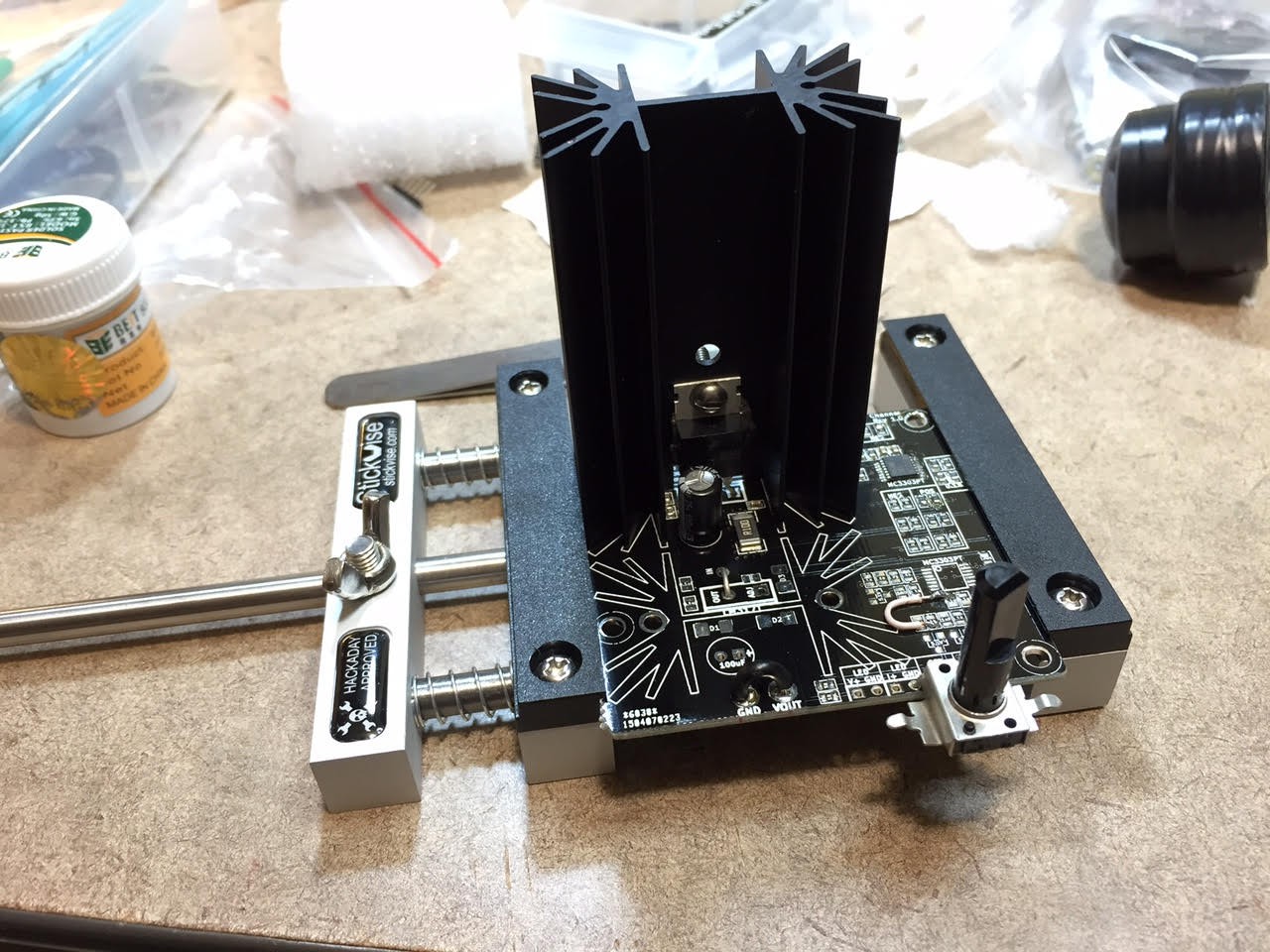
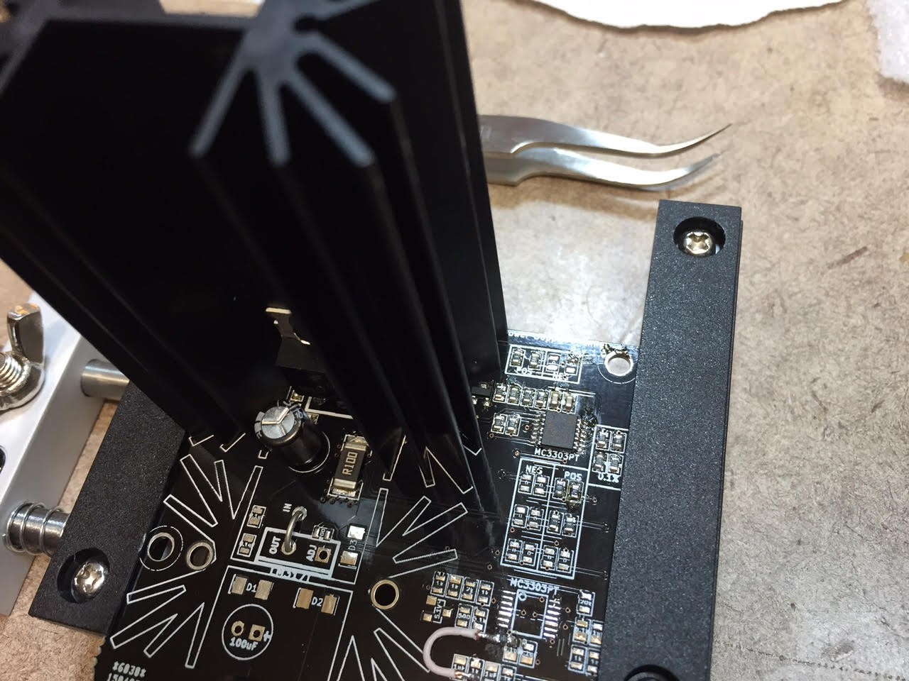
The design uses mostly basic components, with each channel based on the TI LM338 / LM337 with op amps for control. The digital control board runs an Atmel ATMega32u4, and generates the analog setpoints via the Microchip MCP4728 I2C DAC. The same board can be used for either positive or negative output depending on which optional components are populated. (For instance, you would use either an LM338 for positive, or an LM337 for negative; you would use a NPN transistor for current limiting on a negative channel, and a PNP for positive channels; there are different arrangements of 0-ohm resistors used as jumpers to configure positive or negative modes). If you choose to not bother with current limiting you can eliminate the transistor plus an op amp with supporting passive components.
The BOM costs break down as...
Read more » The Big One




 jbb
jbb
 CentyLab
 John Duffy
 Elia
Elia
It is great to see that project is still alive - last GitHub change in 2019! Are you happy with your design? Do you still use it on your bench?
I am about to send PCB to production. Any last changes you'd suggest?