 Enki
EnkiTable of Contents
2. Metadata
A service manual (even an "unofficial" one) needs some kind of revision control. This is provided in the table below:
| Date | Revision | Description |
|---|---|---|
| 2024-01-01 | 1 | Initial revision |
3. Intro
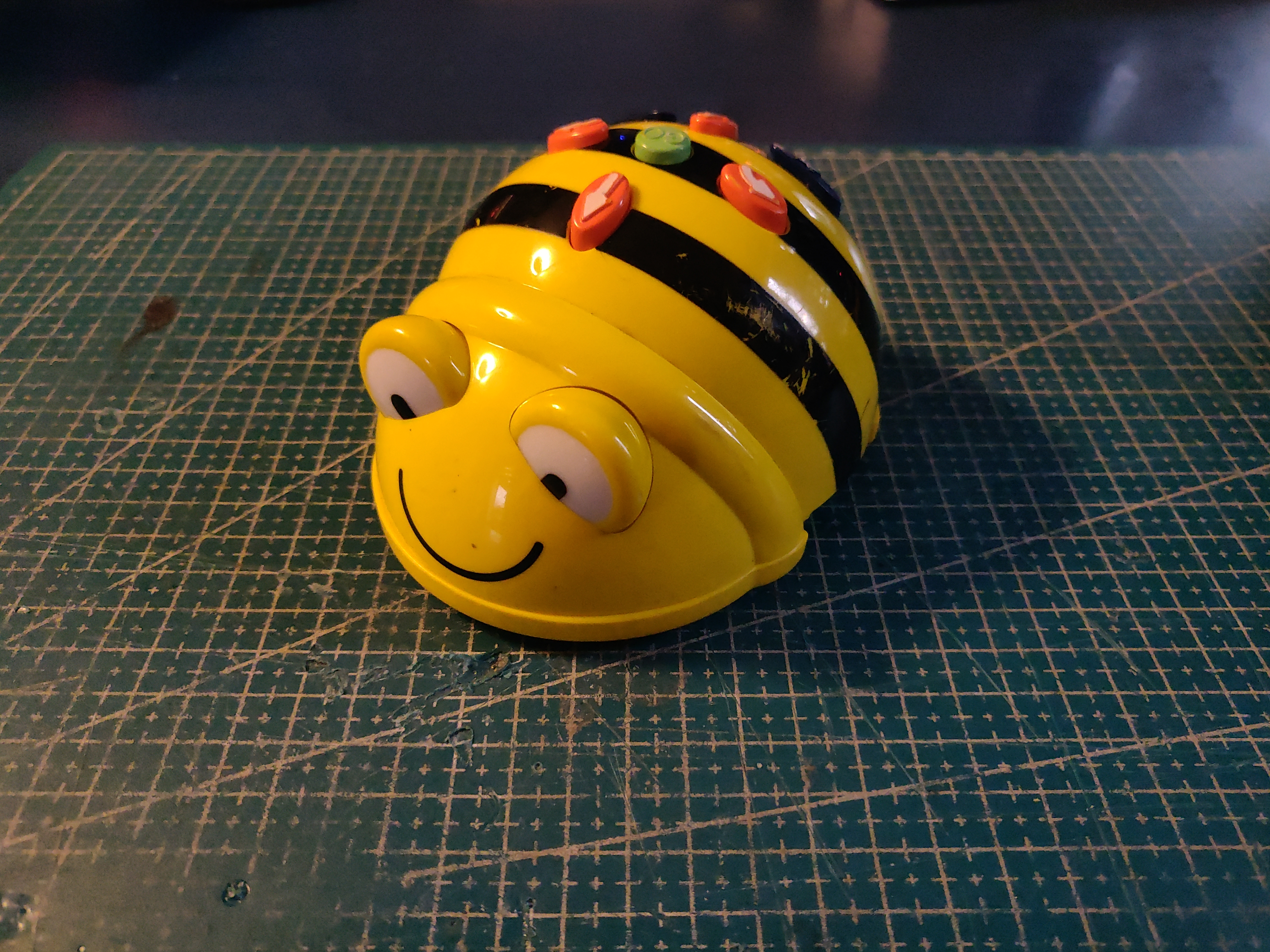
The TTS Bee-Bot Programmable Floor Robot is an educational desktop robot geared towards teaching children simple programming concepts. The robot replays a sequence of movement steps (Forward, Back, Turn Left 90°, Turn Right 90°) which are programmed using buttons on its back. The robot provides audio and visual feedback for the child.
In case it's not obvious, this website is not affiliated with TTS in any way and the Bee-Bot® name is used purely for product identification purposes. This unofficial service manual is (to the best of my knowledge) not endorsed by TTS.
4. Hardware overview
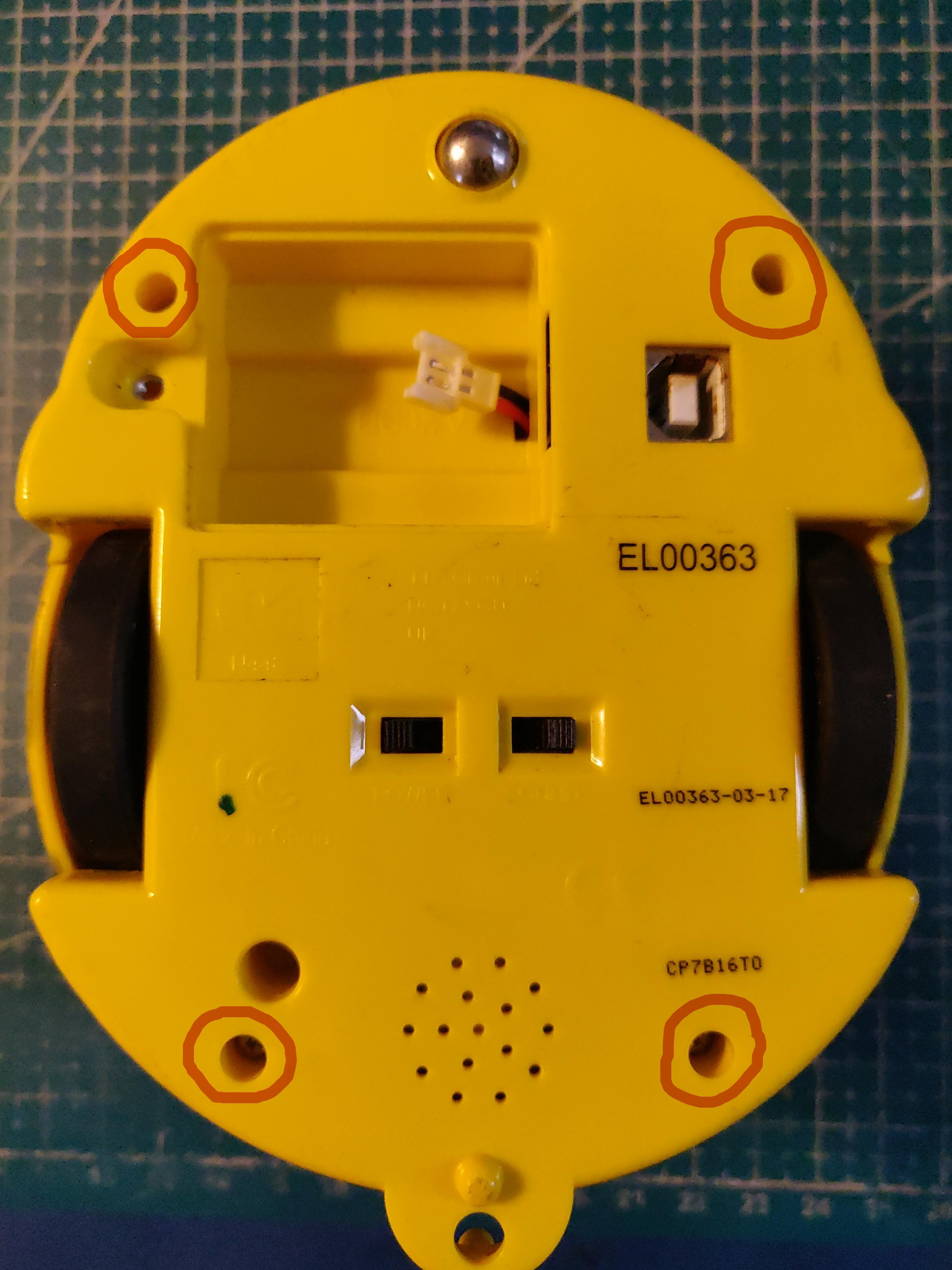
The robot is relatively well designed and easy to disassemble. The bottom provides access to the battery bay, the USB-B charging connector and 4 screws marked with red circles which need to be unscrewed to split the two halves:
A well thought out part of the robot design is that when the top cover is removed the robot can still be operated while having access to it's internals:
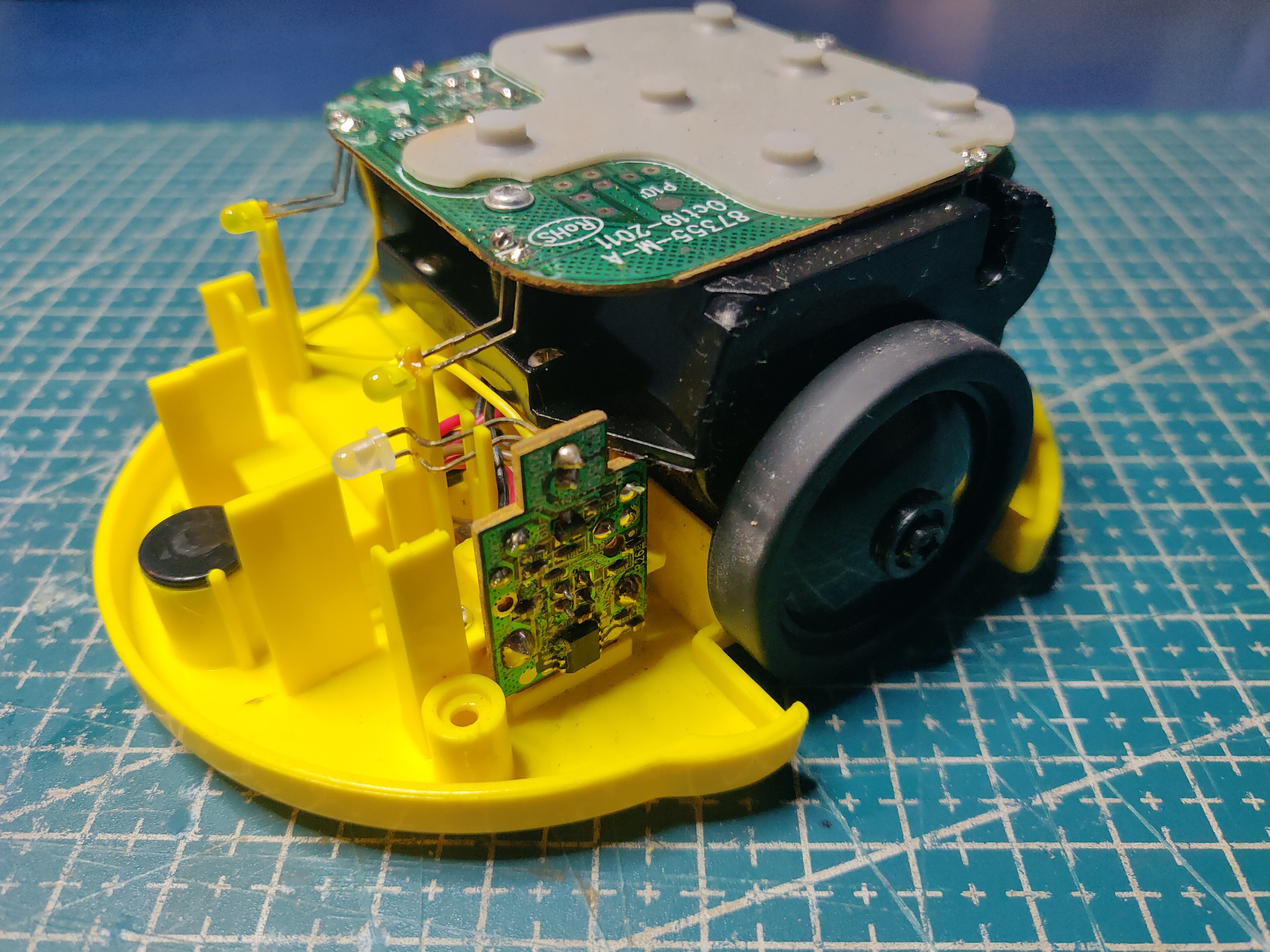
There are two PCBs visible, the horizontal PCB is the main CPU, the vertical PCB is the USB charger board which controls charging and power to the robot.
5. Observed failures
There are two failures which I have seen happen with the robots I've come across:
- inability to charge using the USB-B connector
- speaker stops working
Although my sample size is not large (a small fleet of 4 units), all of the robots have manifested at least one of the above problems. Solutions to both of those have been described in detail below.
Together with those there are also other more predictable issues such as the Lithium-Ion battery loosing capacity over time which is important for an educational toy that needs to work for an entire school day to be usable in classrooms.
5.0.1. USB Charger PCB
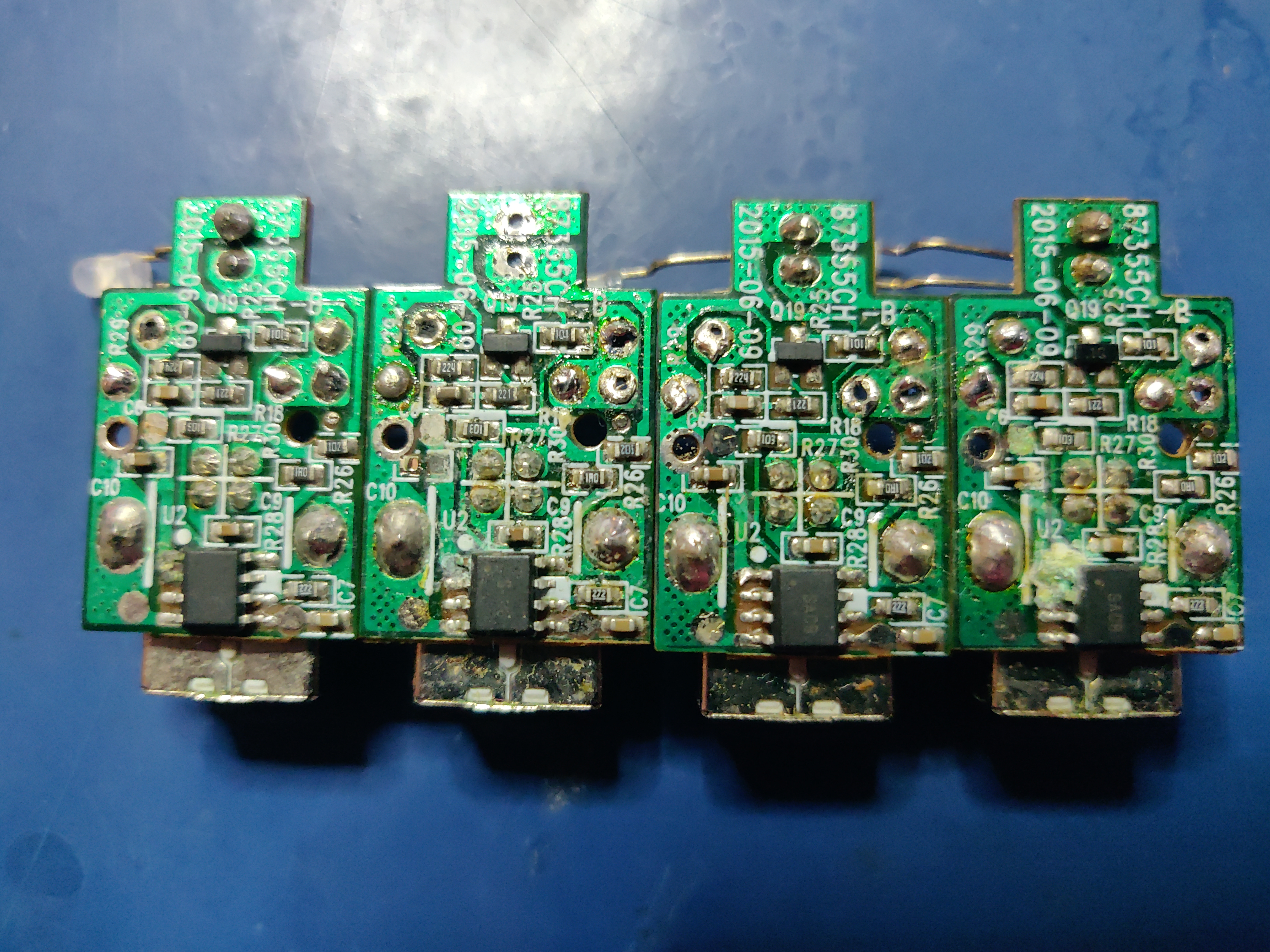
All of the charging failures are caused by a damaged USB Charger PCB board which looks like chemical corrosion. The situation is interesting because the damage on all four examined PCBs looks very similar and no other signs of liquid ingress have been observed:
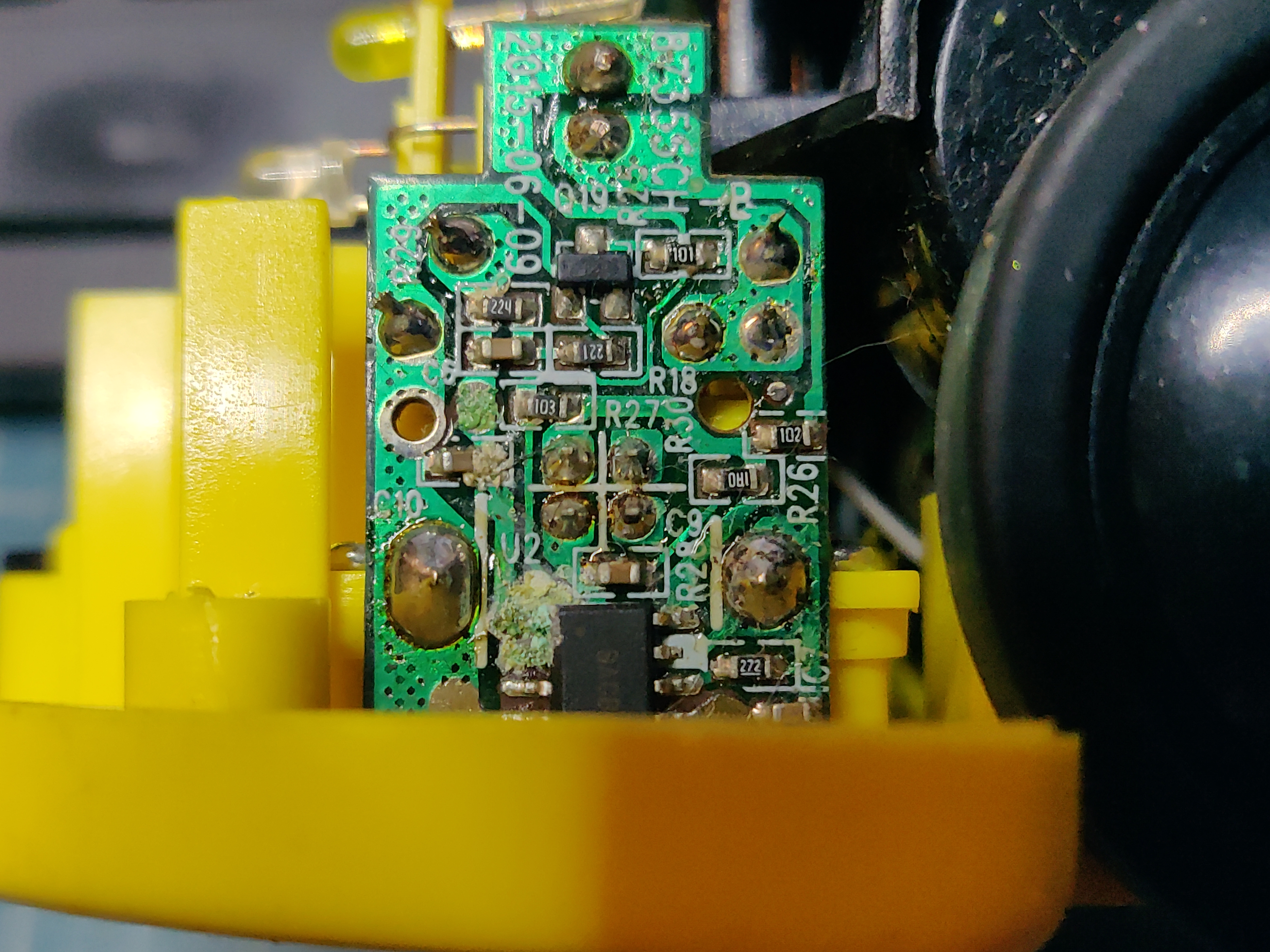
The details of the "corrosion" can be seen in detail on one of the boards still mounted inside the robot:
A replacement board has been designed in KiCad built around the very popular TP4056 charger chip plus some external vanilla components. The schematics for the board is shown below:
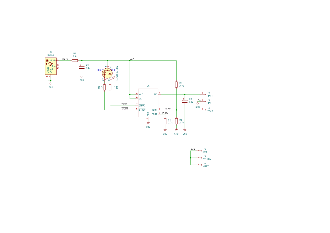
The replacement board has certain improvements from the original, specifically:
- the charging LED is dual color giving a more usable indication of charging state
- the board has the possibility to connect a temperature sensor to the Li-Ion cell, this would however require changing the battery connector and would make the robot incompatible with original batteries
PCB manufacturing has been sponsored by https://www.pcbway.com/ and I must say that the service they provided has been excellent. The traces, drill precision, hole plating and silkscreen quality are top-notch for any hacker's purposes :).
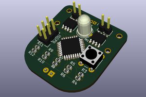
One of the finished PCB can be seen below:
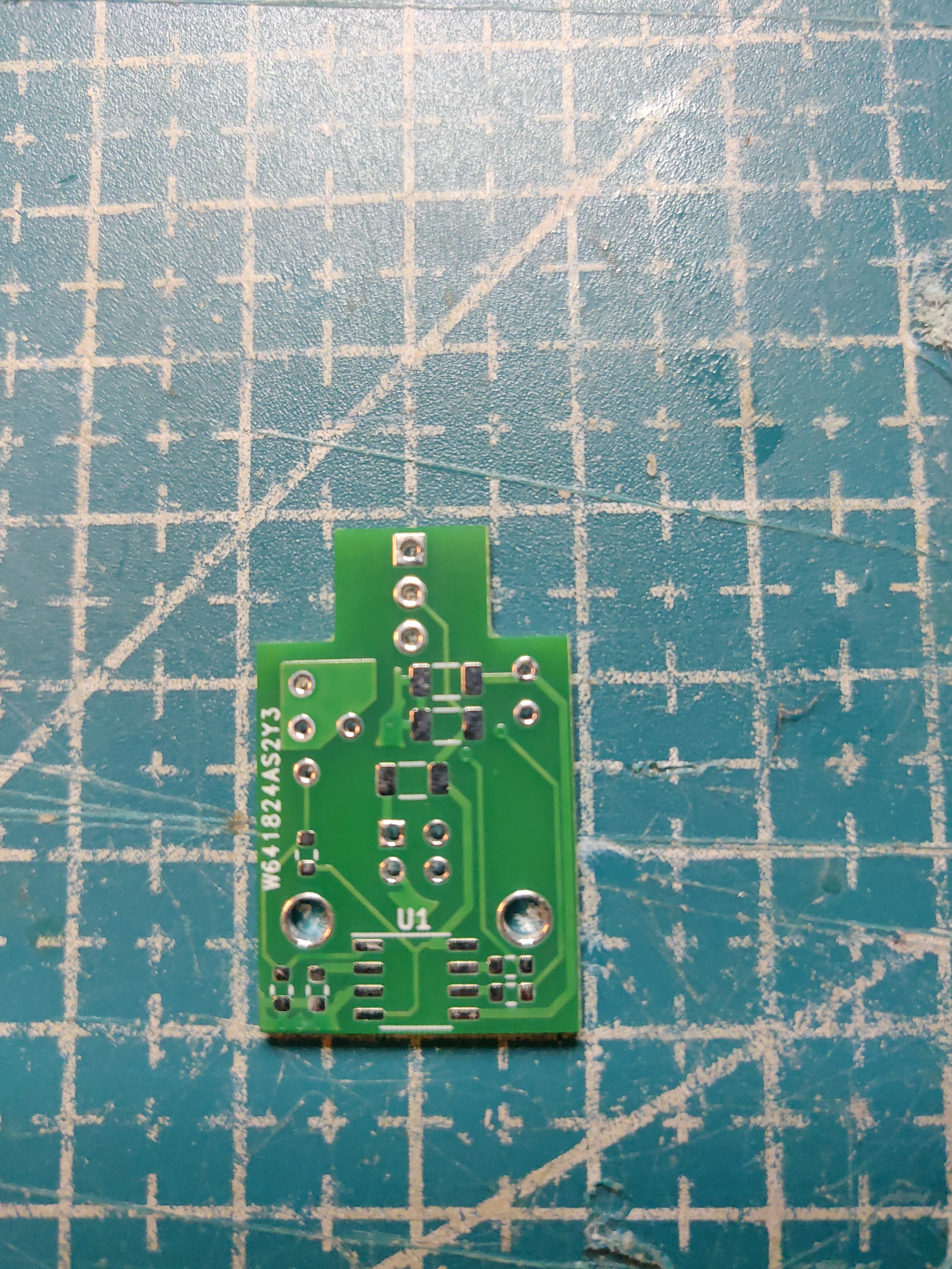
The PCB is two-sided but all of the SMT components are mounted on one side only. The packages used are 1206 and 0603 making it perfectly possible to assemble the board by hand. If you pay close attention you might notice that the original charging PCB has a few extra components which are missing on the new board - a SOT-23 transistor plus a few resistors and a capacitor. Initially I could not properly reverse engineer the purpose or operation of this extra circuit therefore I decided to simply omit it as my testbench tests did not suggest it's...
Read more »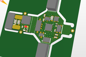
 Joshua Elsdon
 Carl Bugeja
 AmorphousEngineer