See a series of logs with overview of the project:
0%
0%
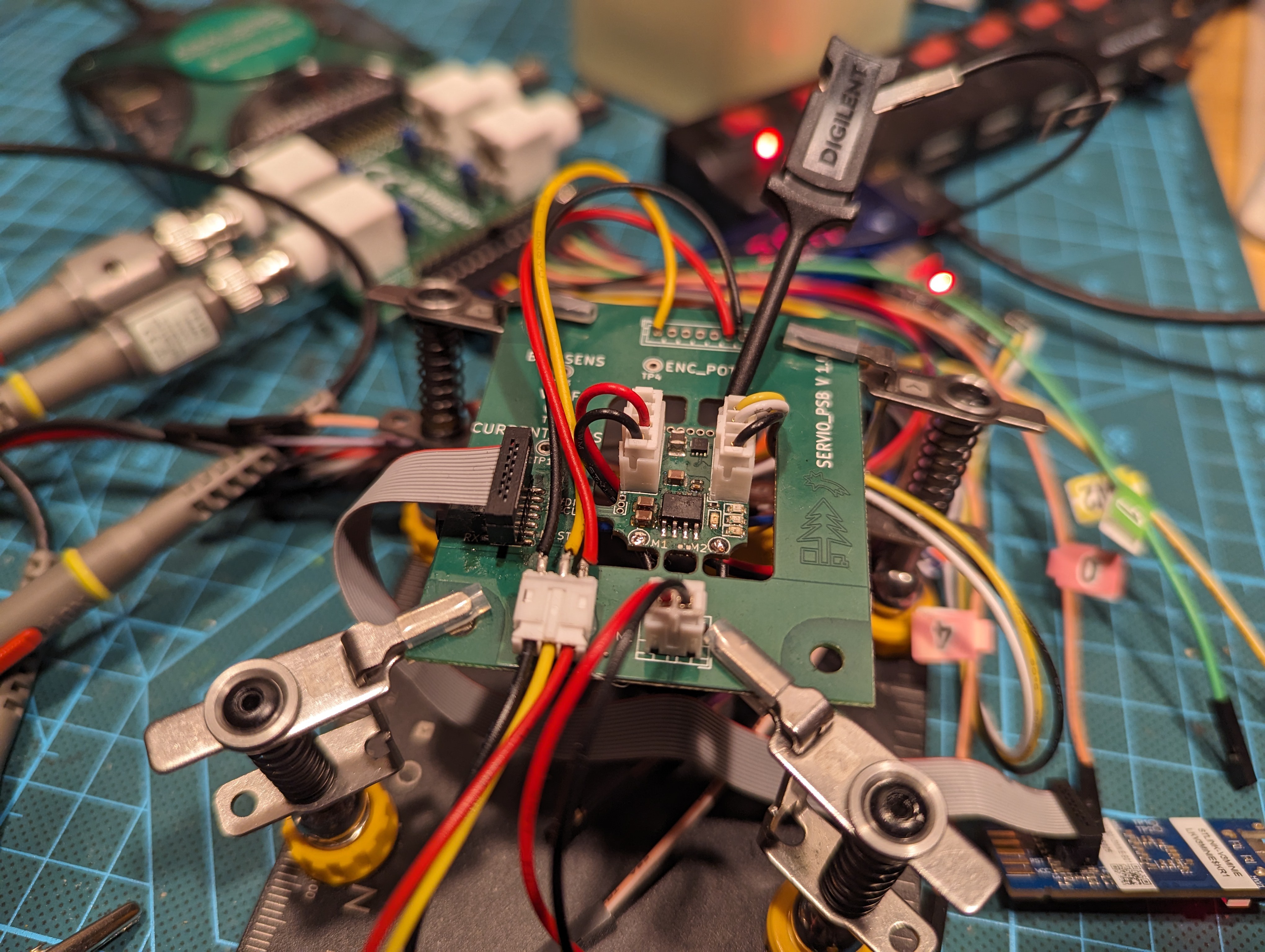
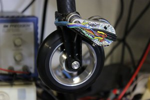
Servio
Open-source DC servomotor with extensive testing infrastructure.
Become a Hackaday.io member
Already have an account? Log in.
Just one more thing
To make the experience fit your profile, pick a username and tell us what interests you.
Pick an awesome username
hackaday.io/
Your profile's URL: hackaday.io/username. Max 25 alphanumeric characters.
Pick a few interests
Projects that share your interests
People that share your interests


 Matthew Moore
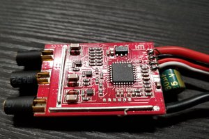
 Anthrobotics
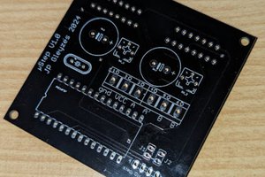
 JP Gleyzes
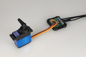
 pat92fr
Nice project! What is this frame?