A special feature of the LED_Watch is its quasi-analog always-on display. This consists of 240 concentrically arranged SMD LEDs (Stanley VCDG1104P-5C63C). Two LEDs light up on the inner two rings in combination with two LEDs on the outer two rings as a "minute hand". On the outer two rings, two further LEDs light up as the "hour hand" and two LEDs flash for 20 ms as the "second hand".
The current through the LEDs, and therefore the brightness, is regulated by the centrally positioned LDR to ensure good readability even in bright sunlight.
The watch has a tilt switch which, when the watch is placed horizontally, reduces the voltage after 12 minutes at the latest by shutting down the LT3459 boost converter to such an extent that the LEDs no longer light up in order to save energy. The watch is powered by a Li-Ion button cell with 3.7 V / 74 mAh, which only needs to be charged after approx. 20 days with a daily wearing time of 10 hours. This is achieved by an average current consumption of approx. 0.15 mA.
The Attiny1614 microcontroller is generally in deep sleep and is woken up every second for approx. 1.4 ms by an interrupt from the real-time clock DS3231 in order to control the LEDs via the 10 shift-and-store registers HEF4094. After 20 ms, it is briefly woken up again by a timer interrupt to switch off the second LEDs. The Attiny is operated at 10 MHz so that it still functions at 3 V.
The watch is set by touch capacitively instead mechanical switch, to make the watch water resistant.
The LT3459 boost converter is operated in a modified form as a current regulator. For this purpose, the current flows from VOUT (5) via VDD (16) of the 10 shift-and-store registers HEF4094 through the LEDs at their outputs QP0 to QP7 back via R5, R7, R6(LDR) to ground.
The boost converter regulates its output voltage via an internal comparator so that VFB (3) - ground is a constant 1.23 V. So there is always a drop of 1.23 V via the series-parallel circuit R5, R7, R6(LDR) which determines the current for the LEDs. There are three times two LEDs in series, which are connected together in parallel. The total current is therefore divided between three LEDs (neglecting the flashing second). The LDR has ~25 Mohm in the dark and ~500 Ohm in the light. The resulting current through the LEDs is ~ between 37 uA and 260 uA.
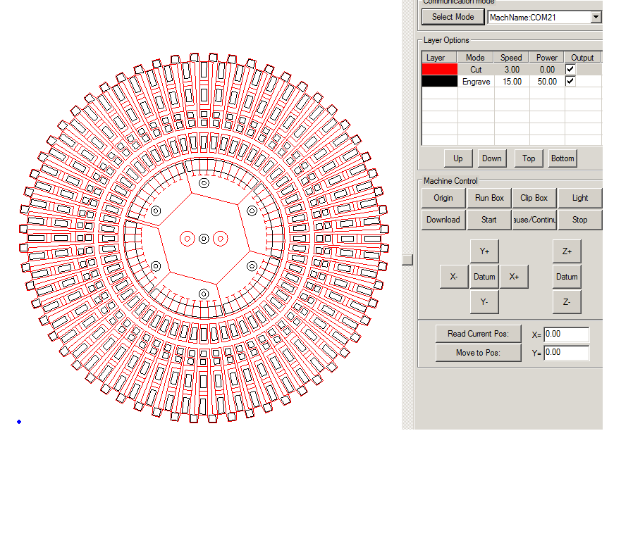
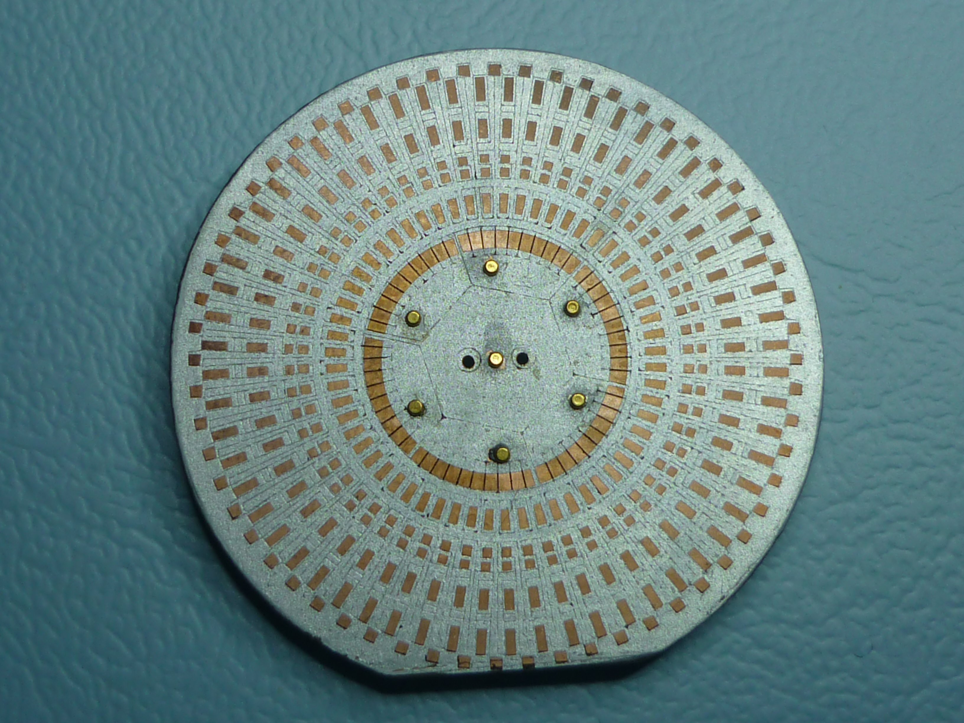
The cathodes of the inner LEDs are divided into six segments of 10 LEDs each. These LEDs1-10 are connected to the corresponding LEDs of all segments, which is why only one LED can be active at any one time. The segments are adressed by the MOS-FET's Q3-Q8. The outer LEDs can be addressed independently, which is why several can be addressed simultaneously. The PCB was produced by laser as under "Dropletwatch / PCB". The red lines are insulation trenches, the black rectangles are pads for the LEDs.

 Christoph Tack
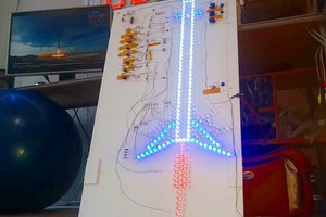
 lion mclionhead
 Glenn.Kubota (gee.k)
I like the wiring job with the enameled copper wires.