

The top plate
On the closeup of the top plate small round pillars can be seen, that have the task, to keep the droplets in their bistable positions. To produce them, the top plate is spin coated with a photosensitive epoxy with a viscosity of 7000 mPa·s (BEST KL6084). To further increase the viscosity, the resin is cooled down to 7°C before spin coating.
Subsequently follows the exposure process by laser and afterwards cleaning with ethanol and acetone. The inner pillars are 0.51 mm in diameter, the outer 0.70 mm.
The whole design is made with LibreCAD and the .dxf file is imported into LaserCad. The structuring of the ITO coating by laser ablation is a very stable process. The isolation trenches are just a few micrometres wide! On the top plate, the three segments of the counter electrodes are used to address the droplets.


The bottom plate
The dielectric is a composite material. First a thin duroplastic foil is hot laminated and afterwards, after removing its thermoplastic cover layer with acetone, cured in the oven at 140°C. On top of this a very thin layer of silicone-modified alkyd resin is spin coated and subsequently cured at 100 °C in the oven. Last step is the spin coating with Fluoropel PFC1601V, to achieve hydrophobicity, which is again thermally cured. The blue watch dial on the dielectric is made of photosensitive epoxy, mixed with blue pigments and exposed with the laser. The 20 conducting bridges over the dielectric are drawn with conductive silver paint and finally sealed with silicone-modified alkyd resin. On the dielectric are two fiducials for alignment purposes with the top plate. This dielectric is absolutely pin hole free and has an over all thickness of 5 micrometres.
The (super)hydrophobic coating:
The solution was the selective, partial hydrophobic coating of trenches with Fluoropel in an superhydrophobic environment, covered with silica nanoparticles. These trenches are 0.5 mm in width, the outer droplet has a diameter of ~1.6 mm, the inner droplet of ~ 1.1 mm
On the closeups below, droplets and their corresponding contact angles can be seen on both surfaces. Please note, that the droplets consist of an (yellow) ink glycol mixture!
In case of water, the contact angle on the superhydrophobic surface would exceed 150°! It was impossible to place a water droplet because they rolled off with the slightest incline of the plate.


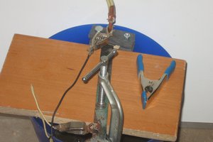
After fixation and alignment, the two plates are sealed, separated by a distance of 0.23 mm, with epoxy resin, except for a small opening. This opening is needed for the injection of the filler liquid and the droplets. The injection of the droplets is a very difficile process, executed under the microscope, because a tiny amount of liquid has to be dosed and placed exactly through the narrow gap of 0.23 mm.Great care has to be taken, not to damage the vulnerable surfaces For this purpose, I had to build a special droplet injector (details under “tools”).
The circuit:
LT3494, a low power boost converter, provides 23 V, which is increased to 46 V (without load) by the downstream voltage doubler. for driving the droplets. U5, MAX6920, is a serial interfaced VFD tube driver. Six of its twelve CMOS push-pull switches are connected to the six electrode connections of the display. U5 can be easily controlled by a SPI interface. U3 is the Attiny1614 microcontroller, that is most of the time in deep sleep and only woken up by user demand or by U1, DS3231, a highly accurate real time clock (once every hour, minute, (second)). U1 communicates with the microcontroller over its I2C data bus. Before going to sleep, the microcontroller shuts down U4, U5 and partly U1 (I2C bus). In this mode, U1 will draw ~ 2 µA and the Attiny in sleep 0.1 µA.
Moving a droplet:
every push-pull switch of U5 can be considered as a half bridge. Two of them build a H-bridge, that can be driven either in phase or phase inverted. As the outputs of U5 are pulsed with 70 Hz,...
Read more »


 agp.cooper
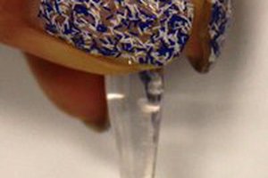
 Adam Gulyas
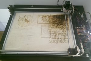
This is some incredible work, well done. I cant wait to see the finished product