 Valdez
Where it all started:
In late 2023, Chamberlain started blocking the MyQ garage door integration from Home Assistant. This move confirmed my concerns about relying on integrations that communicate through cloud based APIs. I begrudgingly overcame MyQ's blockade by soldering smart relays to the pushbuttons of a wired garage door opener and using contact sensors to receive the position status. However, MyQ left a sour taste in my mouth, and since I was also running the alarmdotcom HACS integration for my DSC Neo panel - an integration that warns it "communicates with Alarm.com over an unofficial channel that can be broken or shut down at any time" - I was determined to find a way to integrate my encrypted DSC Neo panel locally so that it would not become the next MyQ.
Neo's encrypted bus blocks any direct integration from non-partners, but I learned from the MyQ blockade that if you can interact with a device physically, i.e. by reading a simple lcd screen and pushing some buttons, no matter how strong the encryption is between that device and its mothership, the information to and from your eyes and fingers must be in an unencrypted form that can then be intercepted or injected remotely. I focused on the keypads, and on building an ESP32 based virtual keypad integration that would sniff the Neo Keypad's lcd screen data bus and hijack the keypad's button matrix. I first documented my journey on home-assistant.io's forum, and now decided to document it here as I continue to refine this project.
Part 1 - Sniffing the LCD Databus:
I knew the H2SLCD Full Message Keypad contained a 16x2 lcd display. I suspected it contained the ubiquitous HD44780 LCD Controller. On opening the keypad I discovered the lcd was on its own pcb which connects to the mainboard with an spongy flexible connector that when examined with a magnifier essentially contains a large number of parallel wires or plates sandwiched between two soft pads that connect the contacts on the mainboard to the lcd when they are pressed together.
I first mapped the contacts on the mainboard to the contacts on the lcd by simply looking where the two boards lined up across the connector. Then with my multimeter I started probing to find what I could. I was able to find a number of Gnd contacts, a +12V contact, a +3.3V contact, and a number of contacts reading varying + voltages between 0-3V. I then turned to the various test points on the lcd pcb. I determined that 6 of the test points connected to an unused footprint labeled "IC3", leaving 12 contacts actively communicating with the mainboard. Of the 12 remaining test points, the first that were easily identified were the cathode/anode of the LCD backlight (labeled K/A at the top right of the board), Gnd, and +3.3V. That left 8 test points unknown. If I was dealing with an HD44780 LCD controller, it would have to be working in 4 bit mode, with the remaining 8 contacts likely being Vo (contrast control), RS (Register Select), RW (Read/Write), E (Enable), and D4, D5, D6, D7 (4 data lines).
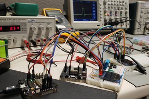
I ordered a 20$ USB logic analyzer off Amazon and started analyzing the signals. I used Logic 2's built in HD44780 analyzer and attempted to identify which signal might be which. I had a good idea which signals were likely RW, RS, and E based on the datasheet, but I was not sure the order of the 4 possible data lines. There could be 24 different combinations in the order of the 4 data lines, and through trial of error, I ran through all the combinations (I went through the 24 combinations a few times only to discover they were in the correct order on the pcb to begin with) and while changing various settings in the analyzer settings, eventually "\x80System Is \xC0Ready to Arm" appeared across the top of the E line! I had successfully decoded the LCD controller and was reading the keypads status with my logic analyzer.
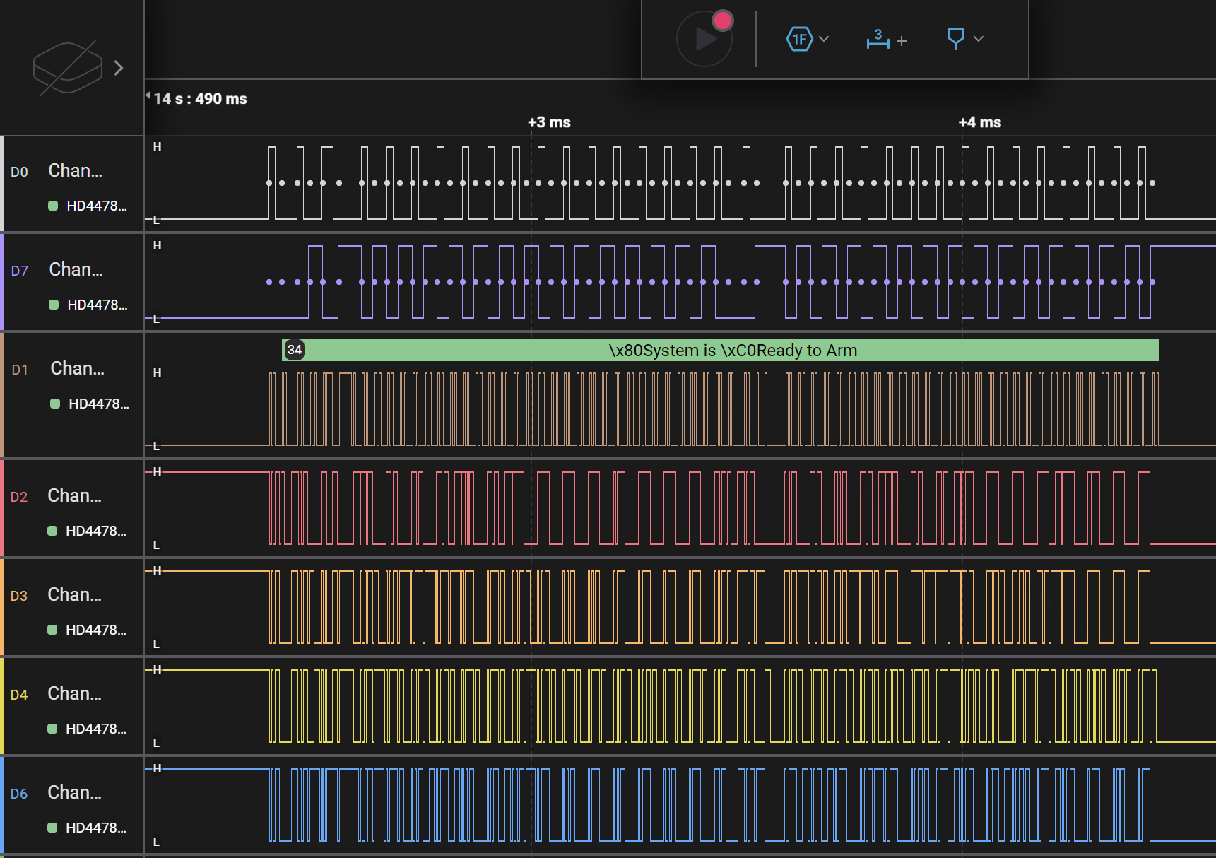
RW = white, RS = purple, E = brown, DB4-7...
Read more »


 David M.
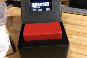
 Albert Gonzalez
 lion mclionhead
 Yadid Ramot
Just wanted to mention I implemented this project with some help from Valdez and it has been great! Used it to get my installer code too.
Pro tip, you can mute the beeps in the user menu.