 Alan
AlanIntro
Hello. I've come up with a groundbreaking idea. It's a USB C-Type Connector that can handle both USB and Ethernet communications.
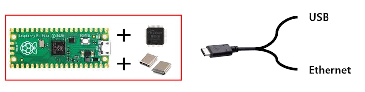
As shown in the above image, I'm looking to create an incredibly compact board by combining the Raspberry Pi Pico board with the WIZnet W5500 and USB C-Type Connector, enabling simultaneous USB and Ethernet communication.
Design
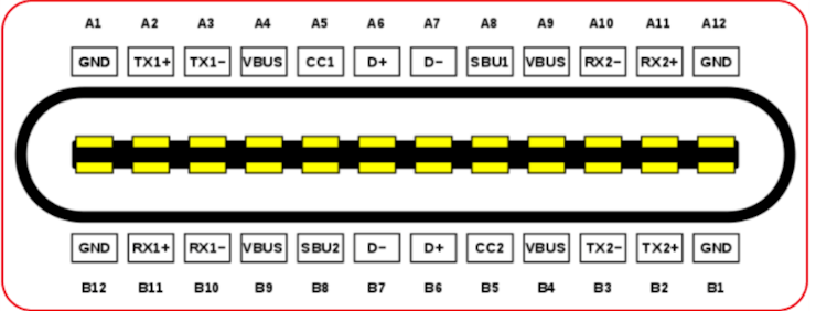
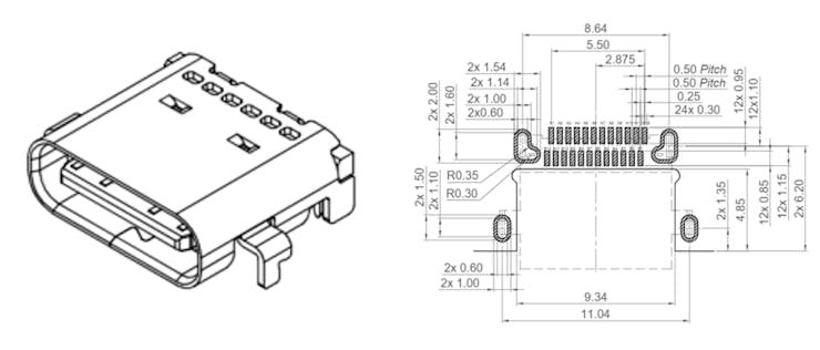
The image above shows the pin map for the USB C-Type connector. It includes USB 2.0 pins D+ and D-, power pins, additional power-related pins, and two pairs of differential lines that support USB 3.0 and above.
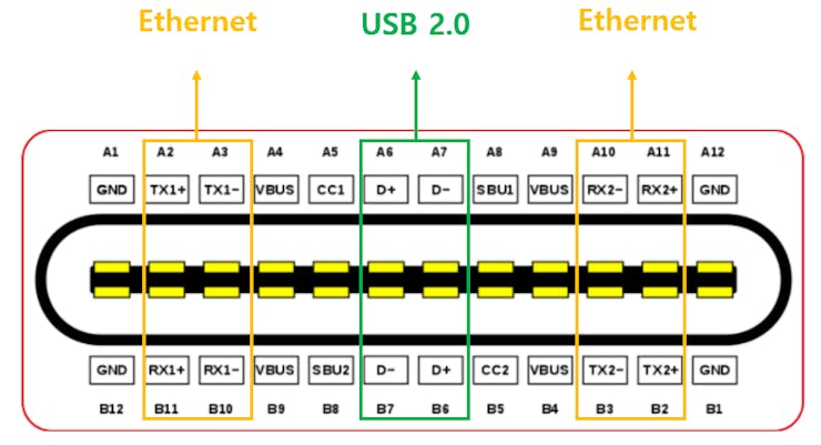
Two pairs of Differential Lines in USB 3.0 are used for Ethernet, and the rest follow the existing use of the USB C-Type.
Impedance doesn't seem to be an issue, as Ethernet operates at 100 ohms, and USB operates at 90 ohms, with the difference being minimal.
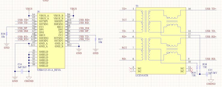
The overall circuit diagram matches the Pico board. The crucial points are as shown in the image above. In any case, an external LAN transformer is needed, so a separate transformer design has been implemented. There were some challenges in designing the MDI circuit, but they have been successfully resolved. I won't go into details.
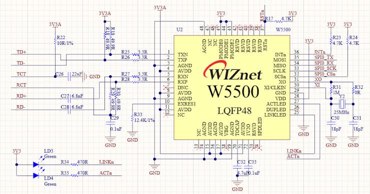
I also design the WIZnet chip in the same manner as described above.
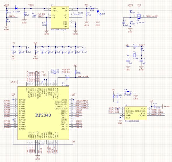
The circuit related to the Pico matches the Pico board circuit.
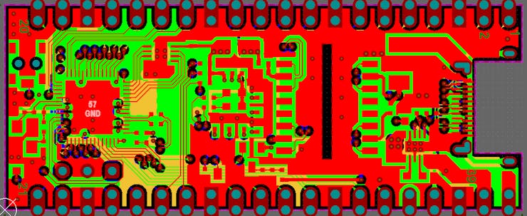
I proceeded with the artwork, and inevitably, I designed the board as a 4-layer board.
I used the USB connector from the product above, but there is an inconvenience in having to change the PCB layout as shown in the PCB image above. I chose the product with the fastest delivery for now, but it seems acceptable to change it later.
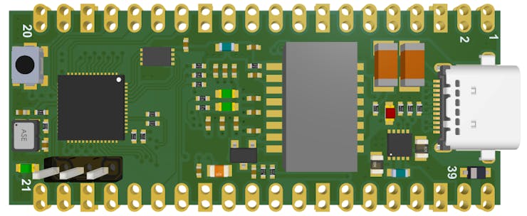
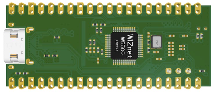
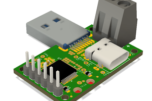
In 3D view, it looks like this. The WIZnet chip is mounted on the bottom side. When the WIZnet chip under development is mounted, there will be no need to attach the chip to the bottom side. However, since it has not been released yet, I will consider configuring it that way later.
PCB Assembly and Debugging
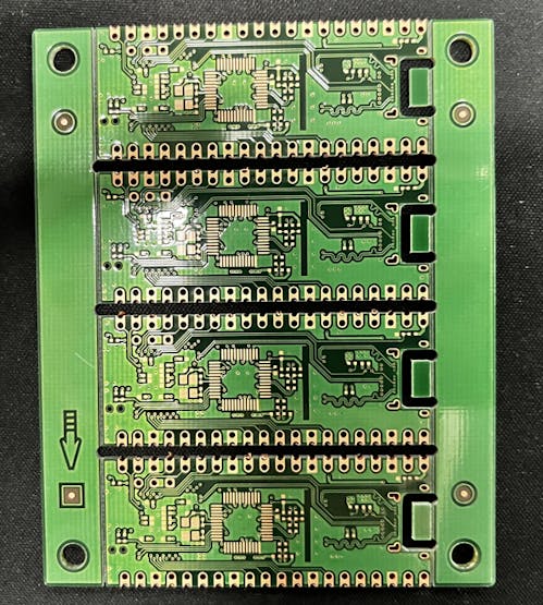
The PCB has arrived.
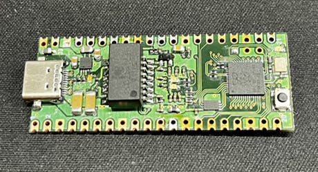
This is the assembly of the front. When I put it together, it doesn't feel as bad as I thought.
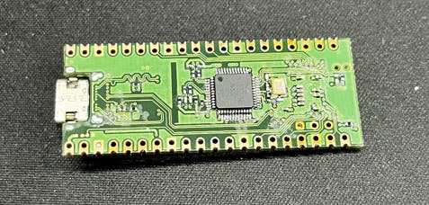
This is the assembly on the back.
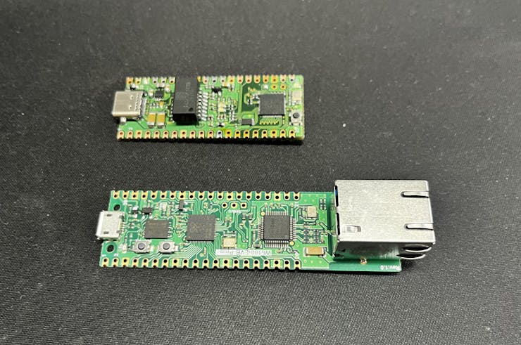
You can see that it's quite different in size from the WIZnet EVB Pico, which has the same function.
Cable manufacturing
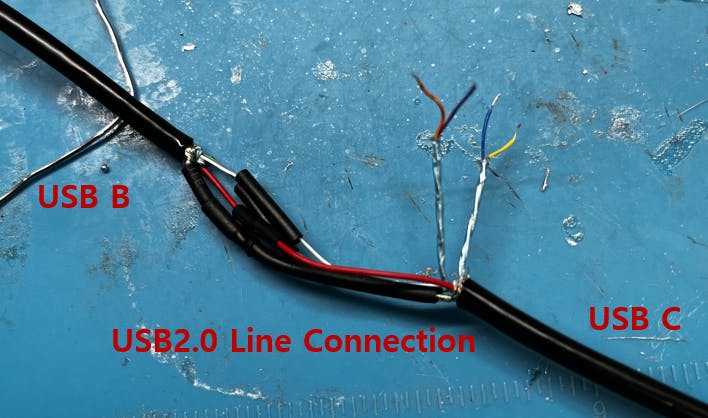
Now, it's time to create the cables. First, to enable USB communication, connect the USB 2.0 lines to a USB B cable.
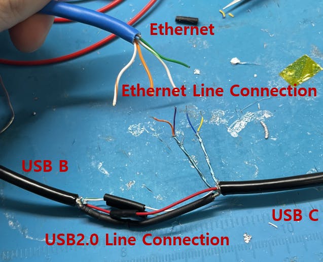
And additionally, connect the Ethernet cable and USB 3.0 lines to complete the setup.
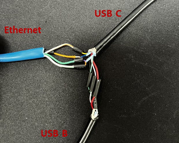
It's completed. The cables are configured like this.
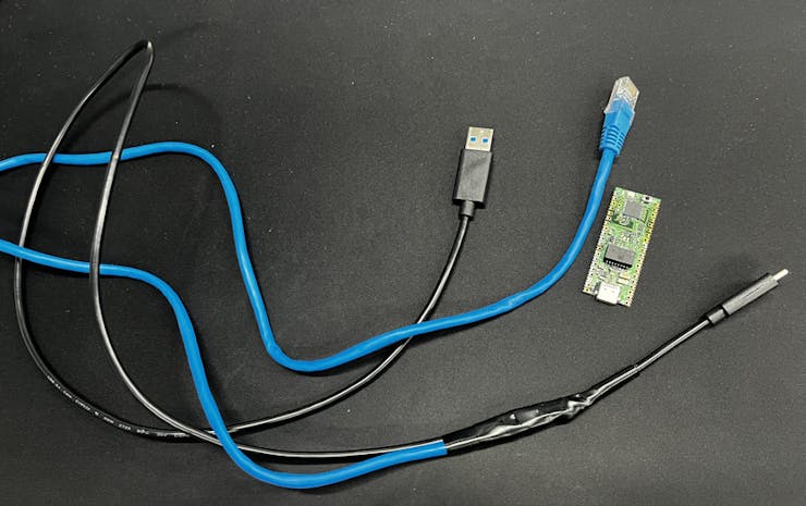
The cables and the Ethernet C Pico are now complete.

When tested, the Link and ACT LEDs operate correctly as expected.
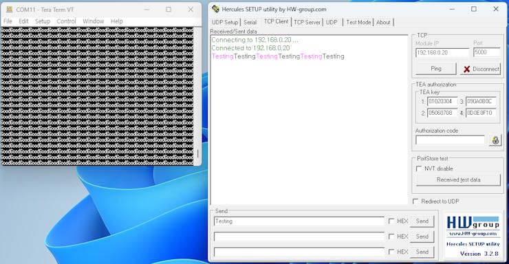
On the left terminal, it is continuously receiving data labeled 'Good' via USB, and on the right tool, it can be confirmed that Ethernet communication is established through loopback.


 Jakob Faltisek
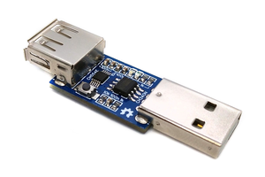
 Stefan Wagner
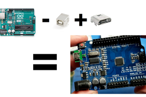
 sjm4306
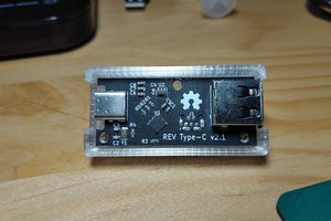
 Thomas Bladykas
Great work.