 potblitd
Why is gifting flowers considered such a beautiful present when the plant will already die only a few weeks or even days later ? On the quest to finding an always-blooming flower, the idea of using PCBs with bright shining LEDs quickly came to the engineering mind. This is one of these projects that involve interesting methods, ingenious workarounds and funky designs that were never even considered in the initial design idea.

Heavily inspired by vyudin’s PCB LED flower, I wanted each petal to have its own microcontroller, that can be removed easily for programming, and hold as many individually controllable LEDs as possible. Having never used the ATtiny microcontrollers previously, I thought it could be a good idea to play with one of these and just bought the cheapest ones I could find : the ATtiny 13A.
Schematics
From its 8 pins, 2 are used for power supply and PB5 is the reset pin that I would rather leave alone because I am not sure what I’m doing, which gives us 5 GPIOs for the LEDs. Now, in order to get more than just 5 measly LEDs to light up the petal, we can use the beautiful technique of Charlieplexing which would allow shining 20 LEDs at once ! At once ? No, not really, but if the LEDs blink one after the other fast enough, nobody will notice ;). So, the circuit for each petal looks like this :
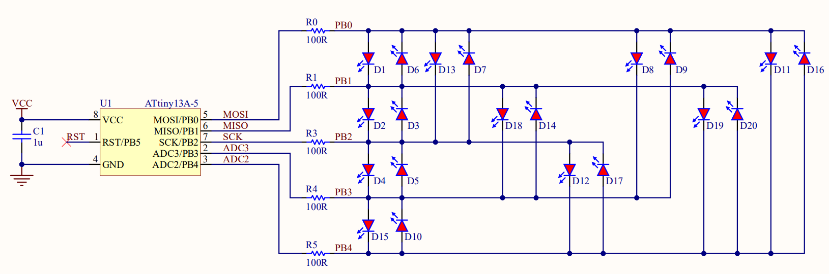
Now for the central part, that holds all the petals, I opted for a single RGB LED in the middle to keep the design neat and small.

PCB Design
The front face of petals and central part accommodates the LED components from the circuits while the down facing side contains the microcontroller and remaining passive components. To allow removal of the ATtiny chip for reprogramming and avoid ugly through hole solder pads, a DIP-8 socket is used. The petals have two ‘teeth’ pads that connect the power supply (VCC & GND) and gives a slight inclination to the petals through the elongated holes in the central part.

Assembly

Code
Before programming the ATtiny chips with Arduino through the USBasp, the libusbK(v3.1.0.0) driver should be installed with Zadig and the MicroCore library setup in the Board Manager, as simply described here. The ATtiny13A features an impressively low 1KB flash and 64B RAM memory, which means that the program actually needs to be lightweight. To achieve this, the code uses PortManipulation and the AVR delay function delay_ms().
The setLED() function can light one LED at a time by adjusting the pins direction with DDRB and the two outputs pins states with PORTB. With this method, all kind of patterns and sequences can be realized. The ‘flower-on’ code below turns ON each LED individually for 1 millisecond, making the flower look fully illuminated to the low-FPS human eye. In ‘flower-random’, the not-so-random Arduino function is used to turn on 'random' LEDs. At first each petal displays the same LED, but since the internal clocks of these MCUs are so inaccurate, the pattern will soon look 'random'.


 Sagar 001
 matt thurstan
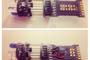
 davedarko
 Jens Hauke