 Jens Hauke
Some time ago i was thinking of how to shrink LED blinkies even more. The first obvious step is to move from 3mm LEDs to SMD. But than there is still this tiny gap between the LEDs which likes to short-circuit with a solder bridge when soldering. Could we avoid this gap somehow? If we connect every anode to the cathode of the previous LED in an LED chain, could we still address every LED individually? Of cause, one GPIO per LED is not an option. It has to be something like charlieplexing. So i start sketching topologies.
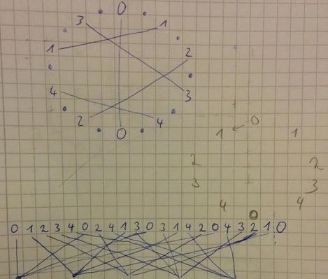
With charlyplexing, every possible GPIO pin pair is used for two LEDs (with opposite polarity). e.g. in case of 2 pins (pin0 and pin1) one LED is connected with its anode to pin0 and cathode to pin1, the second LED with anode to pin1 and cathode to pin0. In short: LED1: 0-1, LED2: 1-0. With more IO pins, you have more pairs and can address more LEDs. With 3 IOs there are already 6 pairs: 0-1, 0-2, 1-0, 1-2, 2-0 and 2-1. In general, with n IOs you could build n*(n-1) pairs. So far, this is Charlieplexing.
As often, if you know how, it is simple. But it took some time to get to this point: We can connect this pairs like domino bricks to build a chain. Again, with 3 IOs we could create the chain: (0-1)(1-2)(2-0)(0-2)(2-1)(1-0) or short 0-1-2-0-2-1-0. The anode of one LED and the cathode of the next LED uses the same IO pin. Voila, they could be soldered on the same pad! For more IOs, it is a little harder to find the IO-pair sequence which builds every possible pair. But there always is one. I really like the simplicity of the resulting circuits and the easiness while soldering this LED daisy chains. Drop me a note, when you build the next beautiful blinky with this technique!
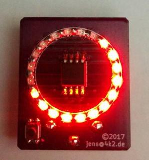
For the LED ring, i use 5 IOs from an ATTiny45 to enlighten 20 LEDs which is the maximal amount with 5 IOs: n*(n-1) = 5 * 4 = 20. The sequence used for this is: 0-1-2-3-4-0-2-4-1-3-0-3-1-4-2-0-4-3-2-1-0
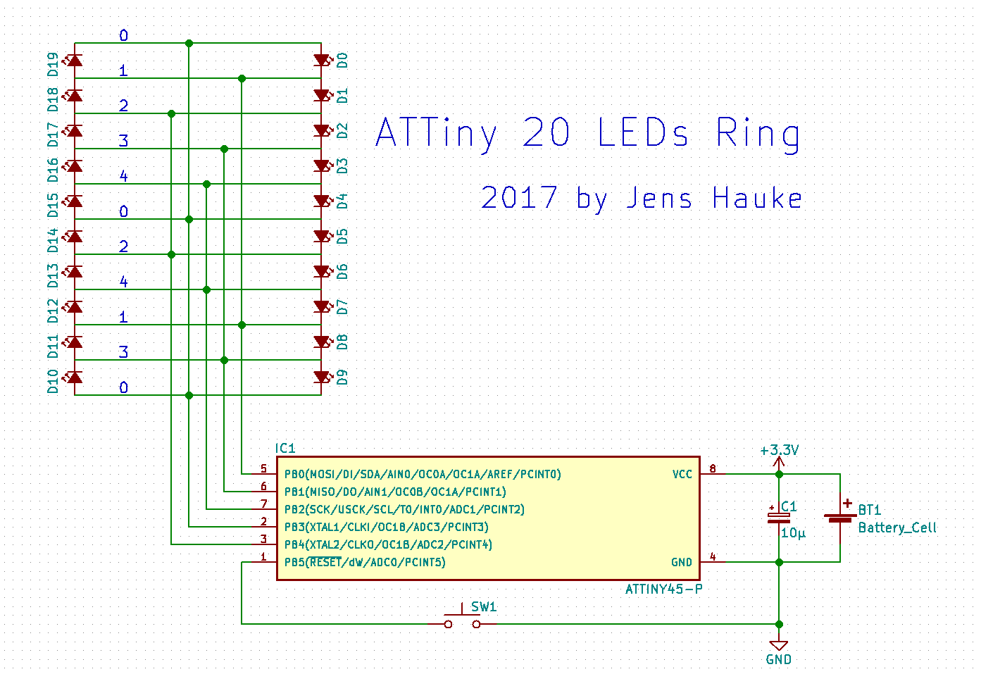
Schematic diagram
You find the schematic for this sequence in the project gallery. I skipped current limiting resistors which are usually used in charlieplexed circuits and rely fully on the internal resistance of every IO pin. This might be out of spec, but i had never trouble with this when running from a 3V coin cell. I like minimalistic designs :-).
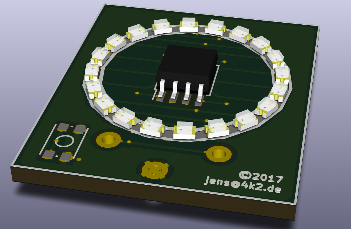
PCB
The PCB is designed in KiCad. KiCad is a great open source tool for PCB design, i can recommend to use! It even renders your toys in 3d with just a click.
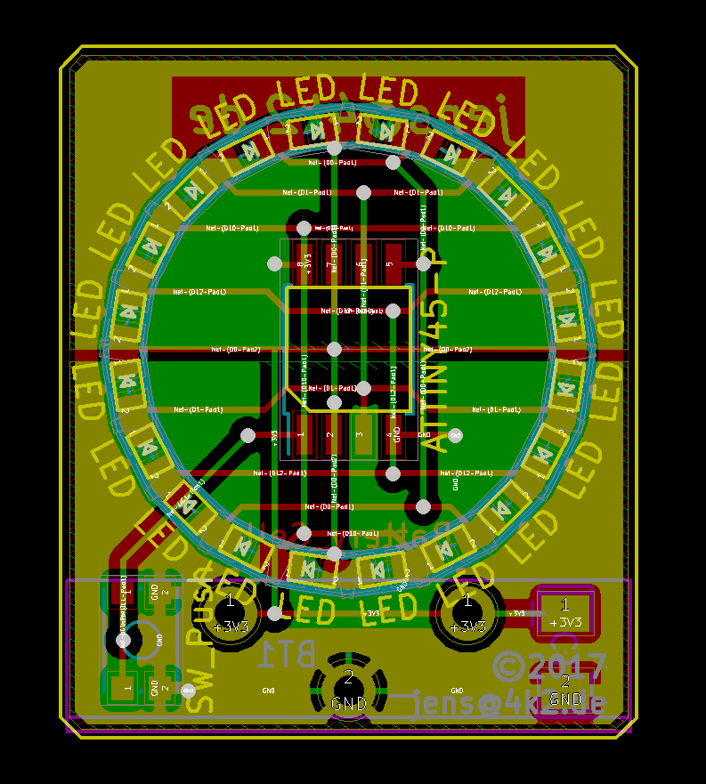
I tried to build something, which looks very symmetric. The front has mainly horizontal traces, the back vertical ones. PB5, the reset pin, is connected to a small push button and not connected to any LED. In the default setup, the button resets/wake-up the tiny from power-down mode and show some animation. After a timeout of 2 minutes, it switches off by going into power-down mode again. In a different setup with the RSTDISBL fuse programmed, this is a weak IO pin and programmed for "power off" and "on" and "animation change". A small bootloader allow serial in circuit programming via PB5 - but this is a different project.
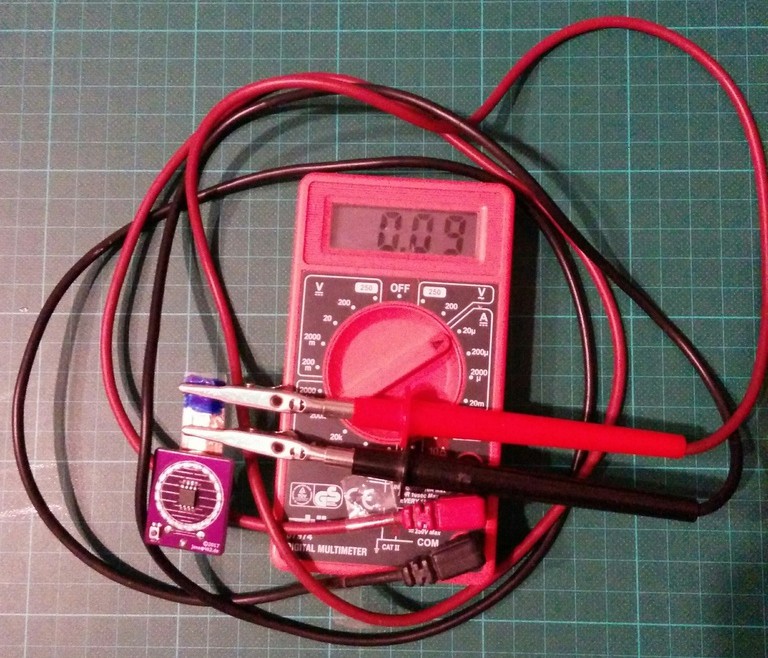
Power consumption
In active mode when running an animation with many LEDs switched on, i measure about 8-10mA. In power down mode (when switched off), my cheap multimeter shows 0.09µA - unsure, if i can trust this value. But the datasheet says, Power-down mode with WDT disabled and Vcc = 3V, Icc is max 2µA. The self-discharge of the coin cell is probably higher. If unused, it will probably last for many years. "If" :-).
")


 potblitd
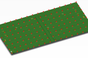
 Mirko
Mirko
 Sagar 001
 Martin Held
Hi, are the Kicad files open to the public ?