 wschneider
Design Details:
- My challenge here is to use as few unique parts as possible, and to keep the BOM approachable for a casual beginner hobbyist.
- I make heavy use of cloned/reusable parts wherever possible, so that instead of printing 5 different items you can print 5 copies of a single item. This creates a sort of ugly effect in the design with a lot of unused holes, but I prefer this to the added complexity.
- I enjoy friction-fitting parts into the slots of the extrusion; Much of the design centers around a kind of block that caps onto the extrusion, and then additional pieces that fit into it. This has been super useful in prototyping since I can reuse that piece in every fit.
- I also tend to prioritize printing without support material. Not because I'm clever, but because I haven't figured out my printer's settings to make support material easy to rip off. A few assembly details (Especially in the shoulder) reflect this constraint.
- All gears are 80 tooth GT2 gears. This gives a 5:1 reduction for both the shoulder and the elbow. This may not be enough, but I have given myself a few other ways to increase torque.
- My initial design I left two gears for the elbow and shoulder, even though only one is necessary. I did this for symmetry because I wasn't sure where I would mount the motor when I started. Now I've left it this way to permit carrying extra motors if I need to increase torque. The shoulder carriage is constructed from 200mm extrusion, and can mount 4 motors in the corners in any orientation. The current design allows a motor placed in any corner to drive any gear. Thus my solution if I need to increase torque is actually going to be to add a motor rather than an additional transmission.
- I've not yet figured out the Z axis; see "Challenges" below.
- I'm also still working on a tool head. My v1 will implement a semi-universal mount based on my cap block, but I will start with a pen plotter as a use case.
Current Status:
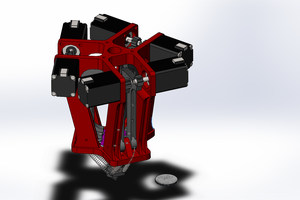
- I have designed and printed the shoulder and elbow as shown in the pictures.
- Almost everything friction-fits together, and with 608 bearings and M8 Screws the Shoulder and Elbow joints move with surprisingly zero sag.
Next Steps:
- I need to find a home for the end stops. I think hall-effect makes the most sense here, since the joints are all free moving, and most other SCARA arms I've seen use it.
- I need to figure out a Z axis situation. I've been designing around the Open Builds gantries for a while, but the more I poke at it the harder I'm finding it to get the lead screw to fit the design. I may have to redesign the shoulder carriage to accommodate a solution.
- I have yet to design a toolhead. I'm surprised with how rigid the arm is - I expected sagging to be a significant issue but using 200mm extrusion for the limbs I haven't had any yet. That may be something that degrades over time under stress, though. At the moment though, I'm not very concerned about the weight.
Challenges:
- I configured the shoulder carriage such that the extrusion sat *EXACTLY* between the gears for the shoulder and elbow. This height choice meant I could mount any motor for any gear in any corner. This doesn't work because the Open Builds gantry I planned on using is about ~5mm wider than the spacing between the extrusions. Thus the mounting holes don't line up properly. If I move the extrusion farther apart, I might need to make custom motor mounts to account for the height difference.
- So far, I haven't had any issues with weight or sag, but once I add the steppers I'm concerned the strain on the Z axis might be substantial. My current plan is to use 2040 extrusion with 2 gantries mirrored on each side. I can then drive the bolt through both plates with nuts and spacers to get the right fit. The Z axis lead screw (s?) would then be mounted to the back side.
- An alternative Z axis mechanism would be to mount...
Read more »
 David Brown
 kmatch98
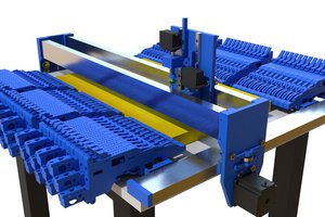
 Christoph
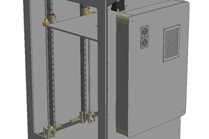
 Patrick
Regarding reduction ratio, torque is not the issue. Resolution is. On my 270mm arm, 8:1 with 0.9 degree steppers is barely enough. I still get visible ripples in prints, but not too bad. Use two stages of your 5:1 reduction. Preferably with 0.9 degree steppers.