 TheBrokenEngineer
There are two versions of this thermometer that vary by power input jack only. One is the standard USB-2 with the through hole socket that is easy to hand solder. The second variant is fitted with a USB-C input jack. This is a little more difficult to solder however the connector chosen has fewer pins that that of a full blown data USB connector so it will be easier to solder with a small soldering iron and a steady hand.
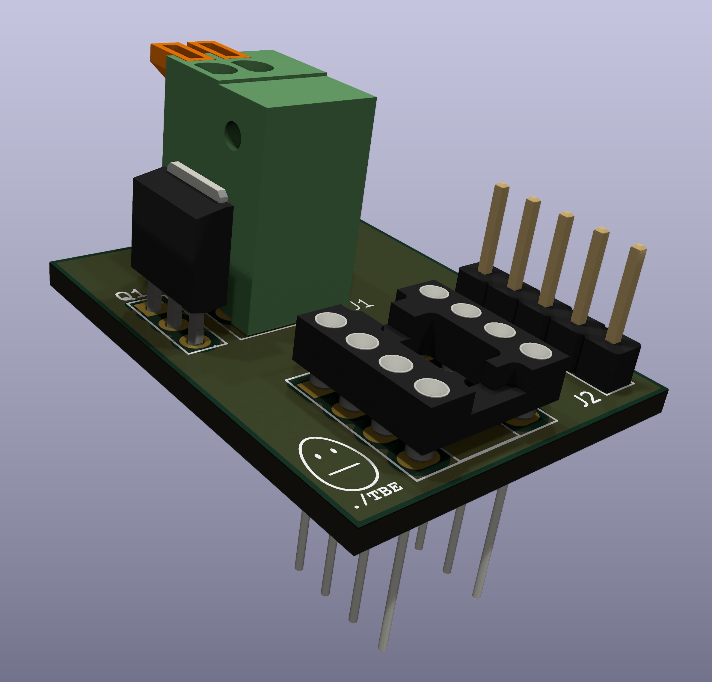
Additionally there is a debugger add on board. This has been created to overcome the lack of programming pins on the thermometer. It allows for both programming and debugging of the software by plugging into the socket that holds the PIC chip. This chip is then plugged directly into the debugger board. I am sure I will get the question "Why didn't you put in programming pins on the board?" and the answer is that we only program once and if that can be done prior to assembly then we don't need the headers and this saves a little cost when making a few of these and it makes the board a little less cluttered.
 WingTechCorner
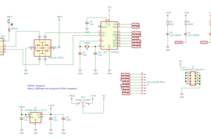
 Zoltan Gyarmati
 Bruce Land
 WestfW