 Jan Neumann
fastLOGIC! open-source (industrial) logic controller

An affordable Arduino-based board designed for straightforward (industrial) logic control, ideal for building small-scale automation and control solutions.
FastLOGIC! is designed to cater to the automation needs of various applications, especially those with modest logic requirements. Its purpose is to streamline smaller projects by eliminating the need for excessive error-prone breadboarding while retaining flexibility and adaptability.
Use cases could be one of these:
- a programmable fridge controller
- water level-dependent pump controller
- a timer that is triggered by a button
- an actuator that activates and moves to an end stop upon receiving a triggering input
- some sensor data you need to display
- a water level sensor/alarm
- you get the idea
Software
The Arduino library can be used to get started. A few example sketches show what fastLOGIC! is capable of how to read sensor data and how to write outputs to the LEDs and relays.
The library covers most cases, but if you want to write or read directly from or to the pins:
// fastLOGIC! pin mapping
DIGITAL_IN_A = D2;
DIGITAL_IN_B = D3;
RELAY_A_OUT = D5;
RELAY_B_OUT = D4;
TM1637_SCK = D6;
TM1637_DIO = D7;
DS18B20_DATA = D9;
LED_B_OUT = D10;
LED_A_OUT = D13;
VOLTAGE_SENS_IN = A0;
BUTTONS_IN = A1;
ANALOG_IN_A = A2;
ANALOG_IN_B = A3;
If you want to use the 7-segment display, use this library.
The part numbers in the KiCAD files are LCSC part numbers. This means you can order directly from JLCPCB using the manufacturing files in the production folder. I typically opt for SMT parts exclusively due to the high cost associated with THT assembly and also because not all the required parts are readily available in stock.

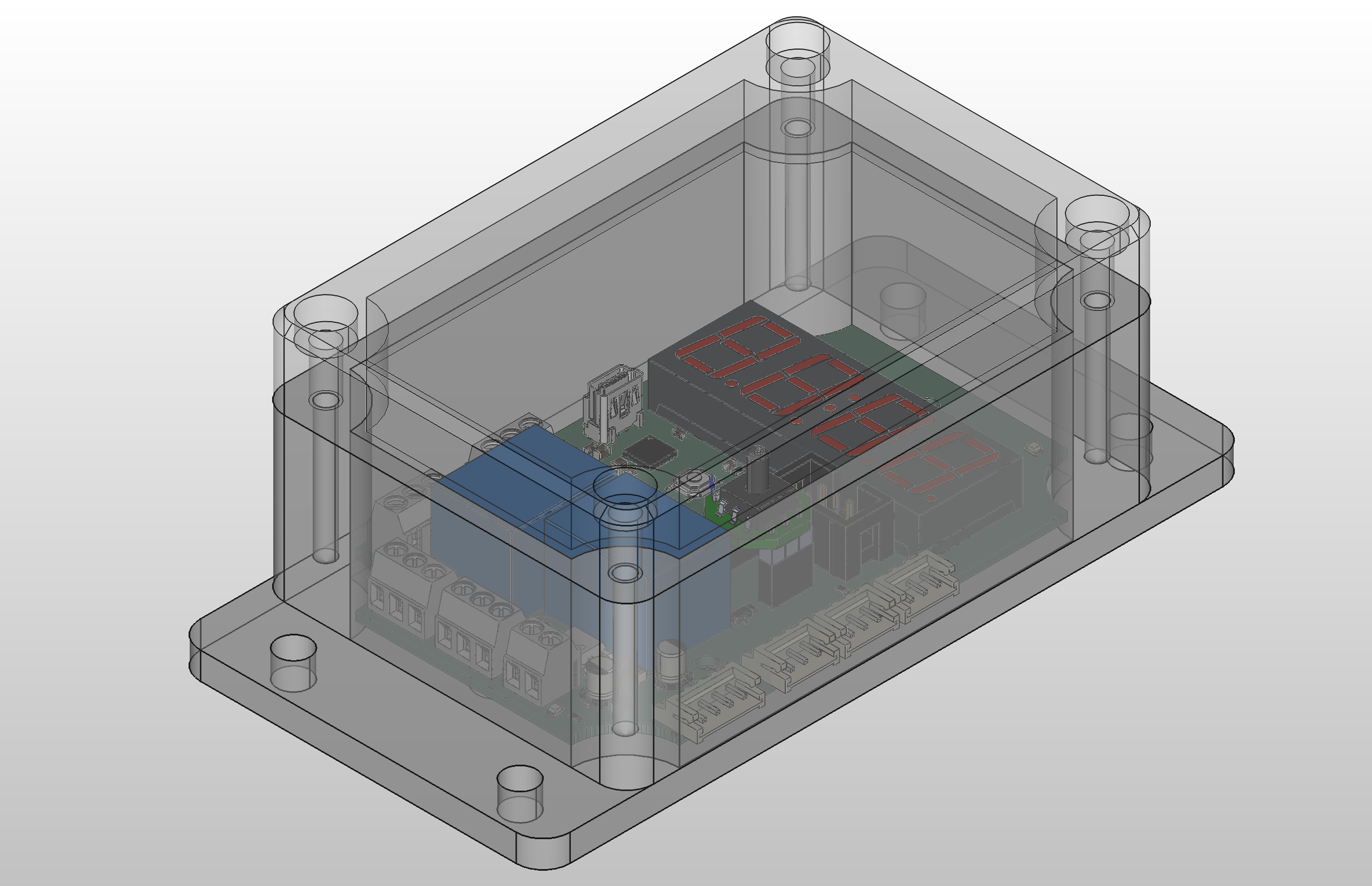
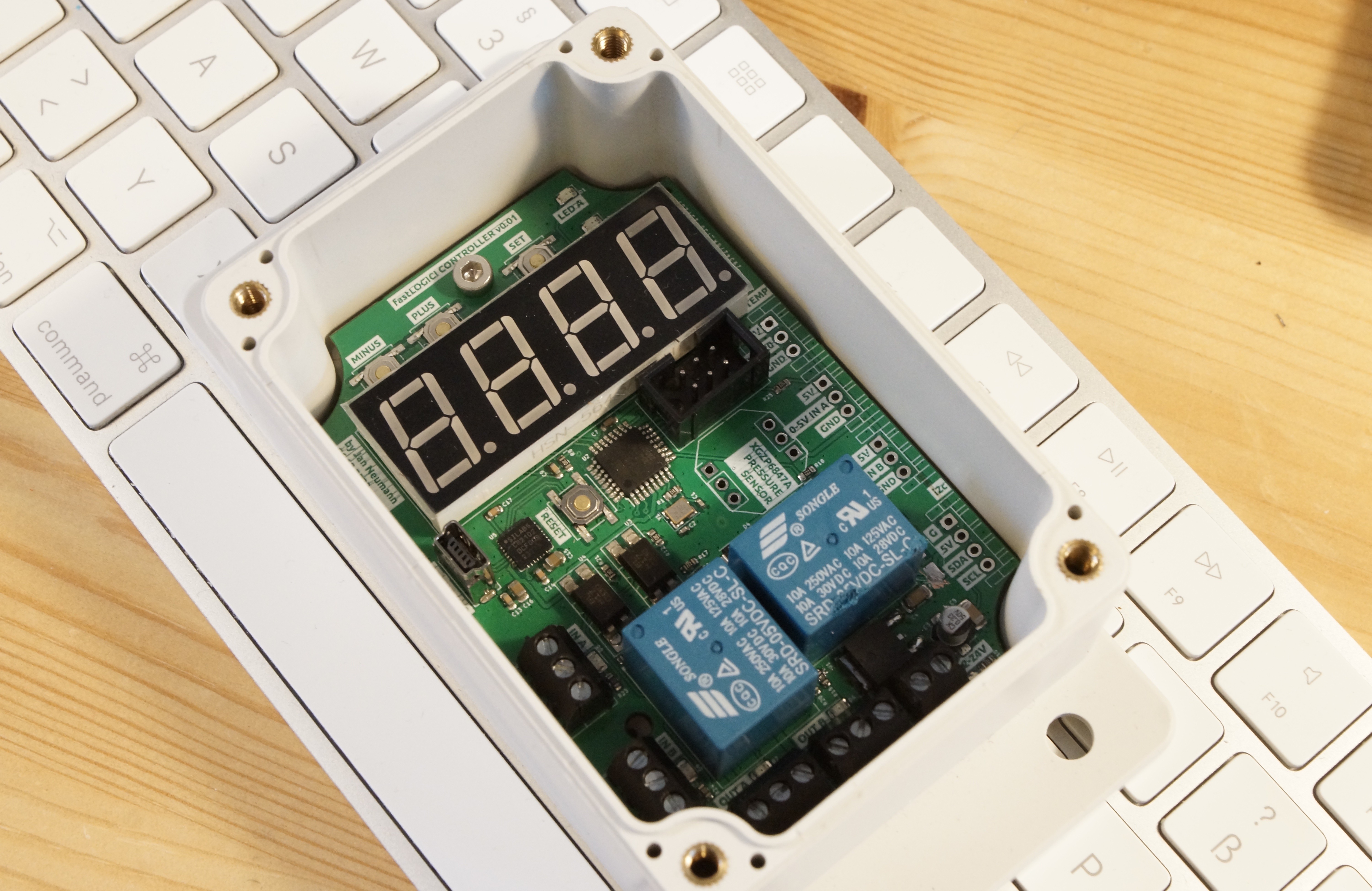
Hardware
The placement is largely self-explanatory. If you are uncertain, refer to the images provided below or utilize the 3D view feature in KiCAD for further clarification.
The only hardware parts you need:
- relais 5V
- 4-bit Common Anode Display
- JST connectors 3pin + 4pin
- Screw terminals 2pin + 3pin
- USB connector Type A
- Case
- an ISP or Arduino in ISP mode to burn the Bootloader
- three 5mm (M3) screws
Optional:
Assembly
Enjoy the project, but keep in mind:
- The project is still under development and is currently in the prototype stage! Keep an eye out for updates!
- This also implies that not all functions are guaranteed to work flawlessly and may not be entirely safe
- Avoid unsupervised usage in a production environment. Utilize at your own risk
- Ensure input voltage is between the range of 12 to 25V. (Currently lacking reverse polarity protection)
- Do not use the relay to switch mains voltage! It's suitable only for low voltage and currents below 5A
Happy building + coding!

 Facundo Noya

 Markus Leutwyler
 Craig Watson