 fool
foolIntegrating Electro-Luminscent (EL) materials into interior lighting makes it possible to design a friendlier lighting system for the mobility impaired.
One useful feature of EL materials is that it is possible to detect touch anywhere along their surface (using this arduino compatible circuit board).
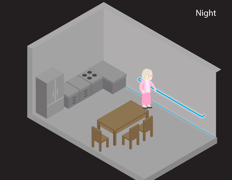
We propose using this feature in combination with motion sensors to create environments where motion activates EL strips that aid in guiding an individual to the kitchen (for instance) in the middle of the night. These strips can be configured to initially turn on in a low brightness mode (to minimize the disturbance from accidental triggering).
If an individual in this environment needs more light in order to navigate, they can get it by simply touching the "rails" anywhere to increase their brightness, or to activate other (possibly LED based) lighting. This improves safety by making lighting environments that more immediately and seamlessly respond to the needs of their (mobility impaired) humans.
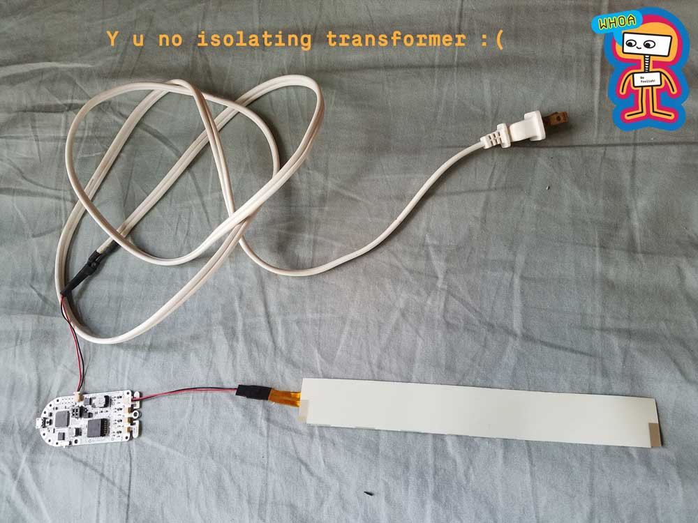
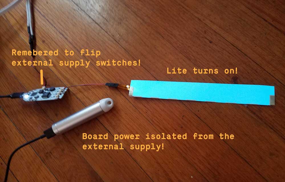
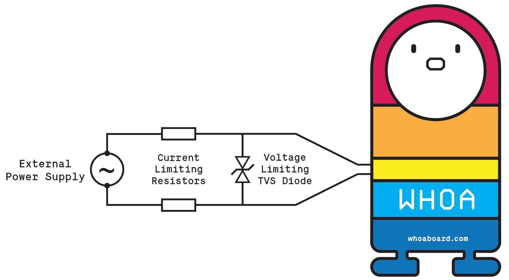
For our hack, we document the development process of an external power supply compatible with the touch sensing functionality of the Whoa Board.
Here is a statement of our main technical challenge!
We then:
Surveyed some existing design resources
Thought about component selection
Gave an example of an experiment that need not be repeated
In our earlier logs, we document the context and design process of this project:
EL background and Assistive Tech brainstorm
Exploring applications and interactions
 As mentioned
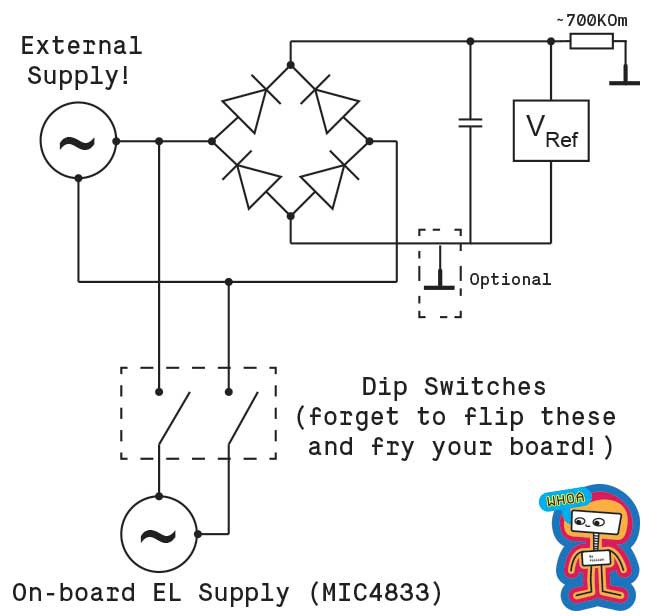
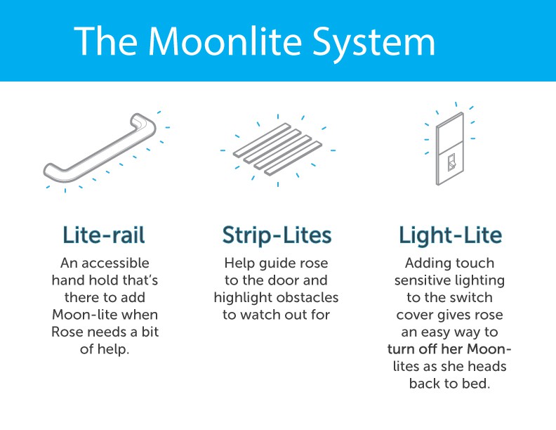


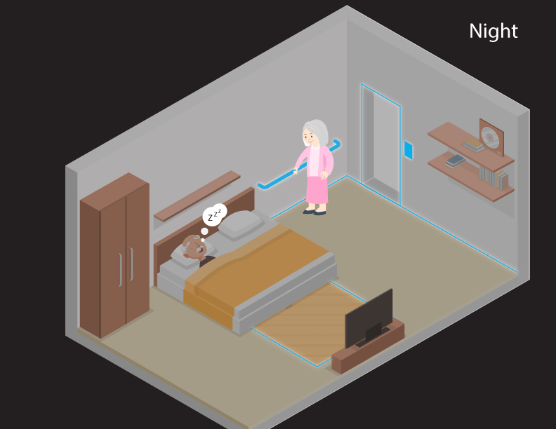 On her way back to bed, she can tap on the outside of the light-switch to deactivate the MOON-LITEs, something not usually possible with a motion activated system or turn on the room lights if she needs to find a book on her shelf.


 Jakob Wulfkind
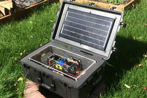
 oneohm
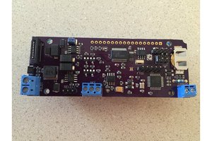
 Nick Sayer
 Tony
Tony
Hi @Wassim, getting to the point of popping this off the stack for a moment. So what I think I'm interested in is experimenting with self-registration. I.e. install several wireless elements, and they all discover each other, and then all attempt to mirror each other's state (i.e. no dedicated master/slave).
The use case I'm imagining is a "synchronized light switch" where you touch one element, and it wirelessly triggers all the other elements in the house, in a "natural" way while minimizing the amount of state you need to maintain in configuration. Maybe you tell the devices a "range" of ports, so that it's possible to isolate devices in one room from devices in the next.
I am also curious to experiment with bluetooth connectivity. According to this video, it does actually seem that it is possible to both send and receive bluetooth instructions using these radios:
Any clue about the voodoo?
Also here is the wireless course I'm following: https://www.cs.utexas.edu/~lili/classes/F17-CS386W/