PKvirus
🌿 What's This About?
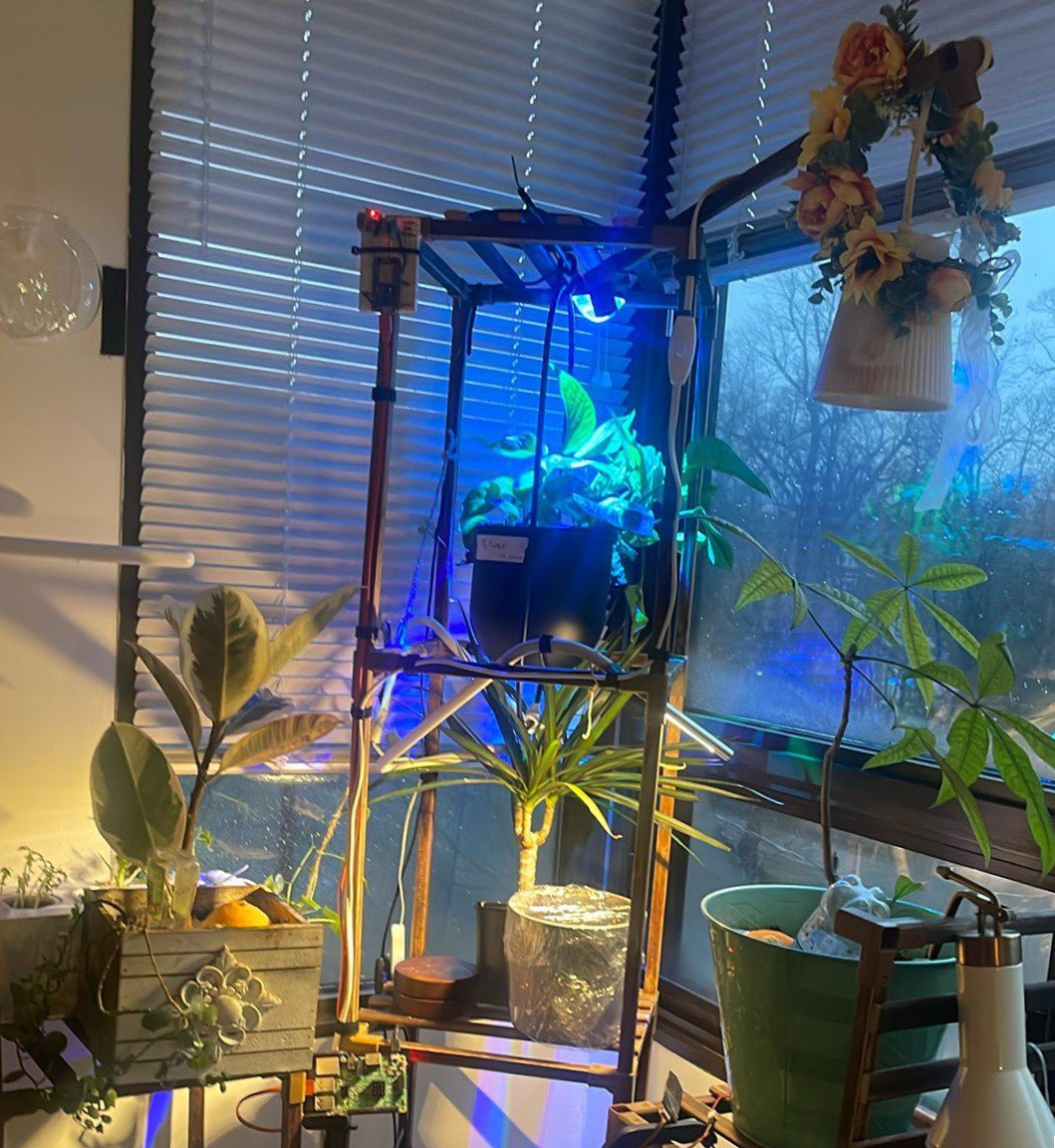
Imagine if keeping your plants healthy was as easy as checking your phone. That's what my project does! It's a smart system that tells you if your plants are too dry, too cold, or just right.
How It Works:
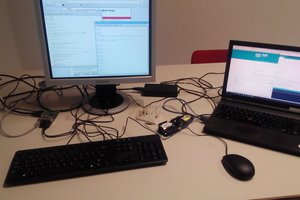
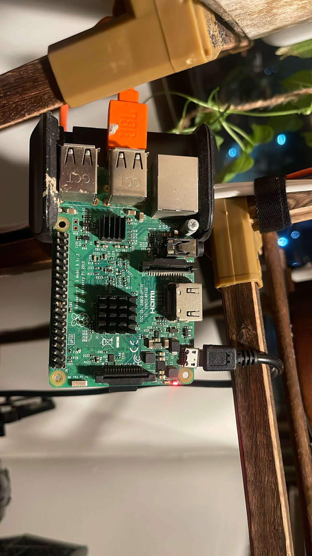
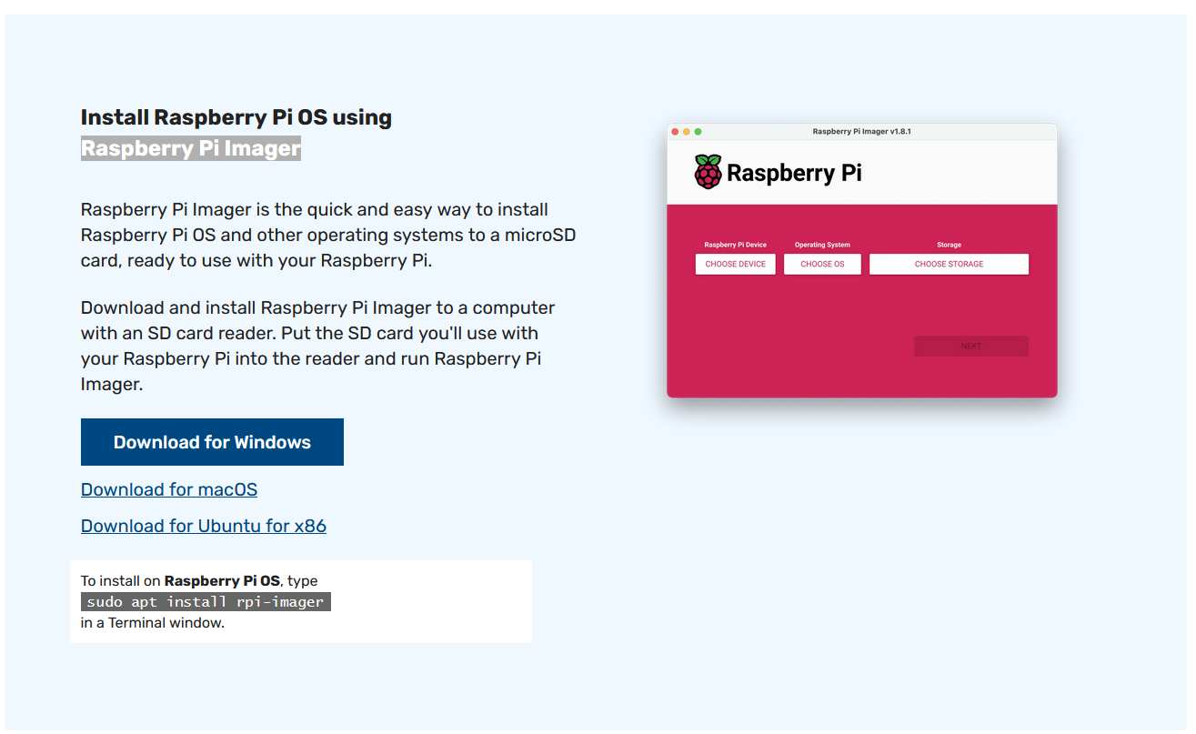
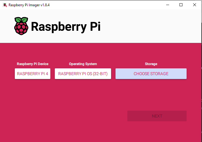
- Raspberry Pi 3B: The brain of our operation, this diligent server gathers, analyzes, and stores environmental data, offering you a real-time peek into the wellbeing of your leafy companions.
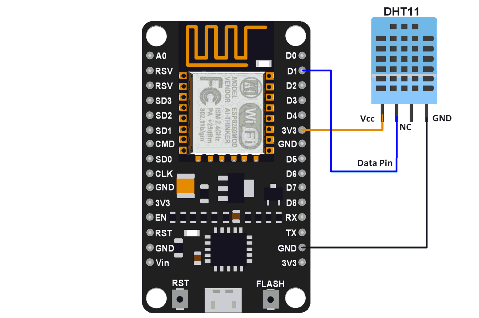
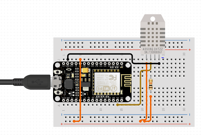
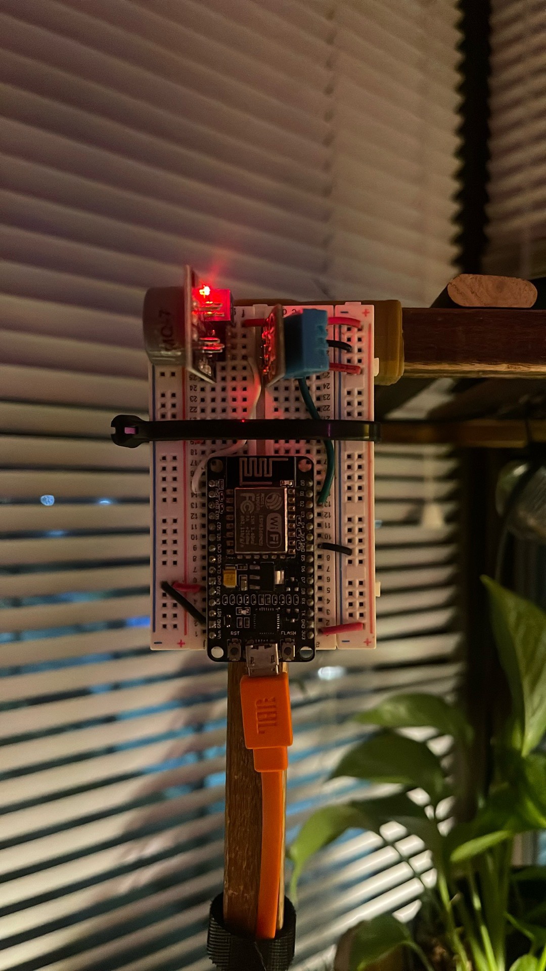
- ESP8266 Microcontroller: Armed with ESPHome, these little wizards get their initial programming via USB but soon take to the airwaves, communicating wirelessly to report back on the climate surrounding your chlorophyll charges.
- DHT11 Sensors: The eyes and ears of our setup, these temperature and humidity watchdogs keep tabs on the air your plants breathe, ensuring they're always in the prime of health.
Cool Features:
- No Wires Needed: After setting it up, the system uses Wi-Fi to keep things neat and tidy.
- Easy Updates: I can improve the system without touching it, using over-the-air updates – it's like magic!
Why It's Great:
This isn't just about cool tech. It's about making it super easy for anyone to make their plants happy. Busy people, plant lovers, or anyone who just wants to start gardening – this project is for you!

 Mario Frei
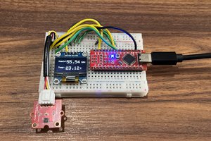
 ElectroBoy
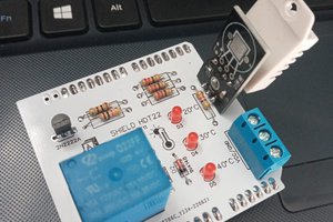
 ElectronicABC