 Look Right
Let me know if this document contains something, what not should be public!
If you have such a board and have details about RTC, serial, DCDC, please let me know!
If you are able to use serial or RTC from software, pleas let me know it!
The main components are:
- U7 + U9: SP3483, SO08, 3.3V Low Power Slew Rate Limited Half-Duplex RS-485 Transceiver
- Q2: SOT23 702: 2N7002, N-Channes Mosfet
- Y1 22.1184 MHz Quarz
- U3: WCH CH432T SSOP20 SPI dual UART
- U8 Sipex SP2323EE True RS232 Transceiver
- U4 Epson RTC R8010, I2C und 2x IRQ
- Q1 NPN Transistor 1AM = MMBT3904L
- U2 1117 3,3Volt Low Dropout Voltage Regulator
- SS34 40V 3A Shottky Diode
- U1 AHHCY6 DCDC regulator
- U12 TXS0102DCUR FE NZ dual Level shifter
- Diode CG_ TVS Diode 28V
- BAT54C SOT23 Marking TL3
- ESD Diode Marking AC: PESD5V0L1BA, Low capacitance bidirectional ESD protection diode SOD323
The known Pins are:
- green LED: GPIO4
- IO0: GPIO17 (5V Logic)
- IO1: GPIO18
- IO2: GPIO27
- IO3: GPIO1722
RealTimClock:
- RTC SDA: GPIO2
- RTC SCL: GPIO 3
- RTX IRQ1: GPIO6
CH432T SPI DUAL UART (connected to RPI SPI Interface and CS0)
- INT: GPIO7
- SCS: GPIO8
- SDO: GPIO9
- SDI: GPIO10
- SCK: GPIO11
 CanHobby.ca
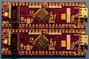
 Yin Zhong
 Sander van de Bor
 John Whittington