 Andy
AndyDisclaimer:
This device is not an accurate measuring device and is intended to estimate the current consumption of the load in dynamics. The measurement error may vary within 1-2 discrete units.
And please excuse my English (I am from Ukraine and my native languages are Russian and Ukrainian).
Development history and a little bit of theory
Sometimes I have to develop and test various autonomous devices. And one of the main requirements for an autonomous device is low power consumption.
Accordingly, there is a need to measure the current consumed by the device. If it is a device that consumes power constantly - you can take a multimeter and simply measure the current consumption.
What if the device is in power saving mode most of the time and only occasionally switches to active mode for a short time? Then the multimeter will not help, because it will not be able to measure the short-term increase in consumption normally.
As an option, you can include a shunt in the power supply circuit of the device and connect it to the ADC through an appropriate amplifier. The converter will sample the current consumption. Samples can be taken quite often, for example, every millisecond. And then these samples can be saved for further analysis.
And if the shunt is built into the feedback circuit of the voltage stabilizer, the voltage drop across the shunt will not affect the supply voltage of the device under test.
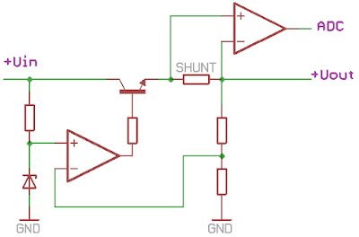
This is an example of a simple voltage stabilizer. The output voltage is compared to the reference voltage through a divider, and an operational amplifier generates the control signal for the regulating transistor. The voltage drop across the shunt does not affect the output voltage because the shunt is included in the feedback circuit.
The voltage across the shunt is amplified and fed to the ADC.
Everything looks very nice, but the first questions arise when selecting the shunt resistance. After all, the device under test can consume 1-2-5 µA in standby mode and up to 50-100-200 mA in active mode.
If you take a shunt with a small resistance, the voltage drop across it at low currents will be small. This voltage will be difficult to amplify without being affected by noise and interference. If you take a shunt with a large resistance, the voltage drop across the shunt will be quite high at high currents. Which will require a fairly high input voltage. In addition, the shunt will heat up due to the high power on it. And heating of the shunt can cause a change in its resistance, which will negatively affect the accuracy of measurements.
Read more »
 Alex Fatiuk
 Marc-O.
 Karel Kouba
 Krists