Silícios Lab
Introduction
One of the elements of great importance for the functioning of hospitals is water. It is essential for several clinical procedures and its control is essential to avoid missing it.
If there is a lack of water, people may fail to perform some medical procedures and may die. To avoid this, it is necessary to monitor the water tank level and control it.
This project was developed for a hospital and its purpose is to monitor the level of the water tank and send a scheduled alert on the water levels in a water tank. From this sent level, the team will know when the level is close to the minimum value and will be able to contact a water tanker to supply water to the hospital.
The proposed project consists of using 3 level switches (minimum, medium and maximum) to monitor the level of the water tank and send alert information via email or WhatsApp to a hospital maintenance department.
Next, we will begin explaining how the electronic project circuit works.
Electronic Schematic of the Project
Below we present all the blocks that form the electronic schematic of the circuit. They are: power supply circuits, voltage regulator circuits, connected board signaling circuit, ESP8266 configuration and programming circuit and connection interfaces for the level switches of the electronic project.


Next, we will begin explaining the power supply circuit of the electronic project.
Power Supply Circuit
The project's power supply circuit is designed for an input voltage range of 7V to 9V. This voltage will be regulated to a value of +5V and then passed through the B0505S device circuit.
What is the purpose of this device in the power circuit?
The B0505S is an isolated DC-DC converter. In other words, it converts a 5V DC voltage into another 5V DC voltage isolated from the input. This allows the circuit on the other side to have greater immunity to noise and electromagnetic interference, as they are 2 different grounds.

Therefore, this second voltage of 5V passes through a +3V3 regulator to power the ESP8266 circuit. Next, we present the ESP8266 circuit.
ESP8266 Configuration Circuit
The ESP8266 circuit is made up of 3 blocks: the ESP8266 with the configuration resistors, the block with buttons for programming and reset configuration and, finally, the pins for code transfer. See the representation below.

From this basic circuit, you can add other circuits from your project to the ESP8266. In our project, we added the reading circuit for the 3 level switches that will be installed in the water tank. See below the circuit for connecting and reading the level switches.
Sensor Connection Circuit
The sensor connection circuit was designed to be completely isolated from the ESP8266's digital input pins. The objective is to provide safety and prevent any electrical surge from damaging the CHIP structure.
For this, 3 PC817 optocouplers were used to guarantee electrical isolation between the sensors and the ESP8266 CHIP. Below we have a representation of the circuit.

As can be seen, in addition to presenting electrical isolation, there is complete isolation between the ground signals of the circuits (AGND and BGND).
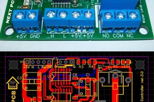
From this electronic diagram, the layout of the printed circuit board was developed.
Printed Circuit Board Layout
Following the layout recommendations and usage rules of the ESP8266, we developed the printed circuit board below. It is made up of 4 layers.

Following the layout recommendations and usage rules of the ESP8266, we developed the printed circuit board below. It is made up of 4 layers.
Brief we'll develop the control algorithm for the electronics project. For this project we can use several methods to access data and monitor water tank levels. In this application we chose to use a WhatsApp messaging system to inform and alert the user when the water level is below normal. This will alert maintenance teams to fill the water tank with the help of a water tanker....
Read more »
 ElectronicABC
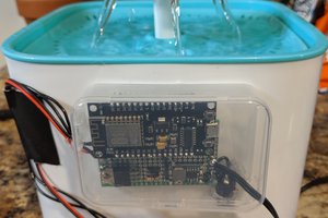
 Technical RC Sharma