 core weaver
Schematic and PCB
the whole designed is "centered" around the double stepper motor BKA 30d-r5. I ordered a few of these motors, drew the footprint and the electrical symbol, then drew a 3d model of it and started to work on the electrical schematic.
I used H-bridges to drive the stepper's coils initially. But after receiving the steppers I measure the current draw, did some experimenting with different loads on the shaft and I decided to make som
changes. The most notably one, I scratched the HBridge drivers and decided to drive the coils directly from the microcontroller.
The brain of the whole system is the ATMega128a which has enough IO pins. The RTC I used, is a DS3231 with backup battery.
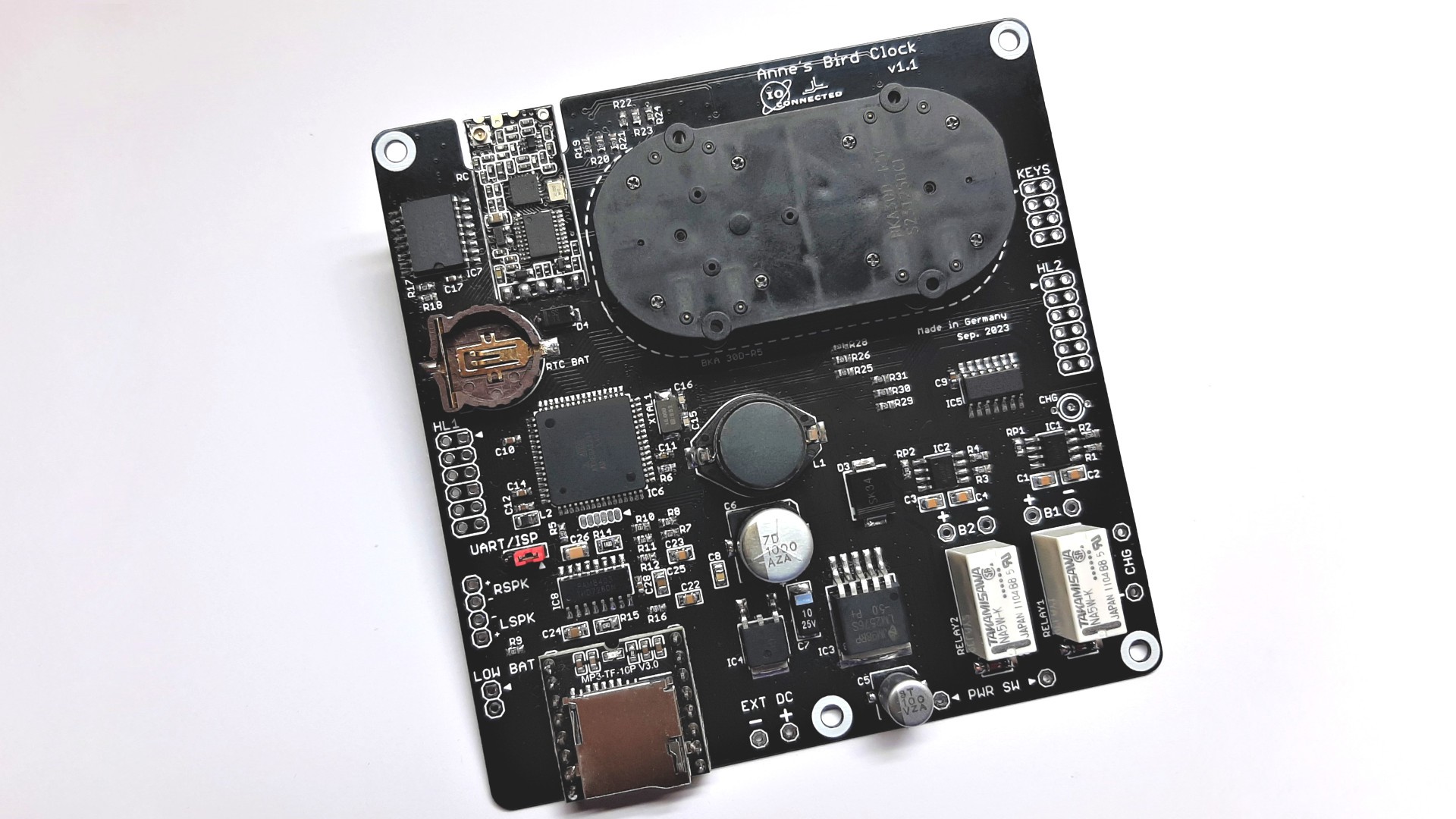
(2 Layers, 100mm x 100mm PCB's)
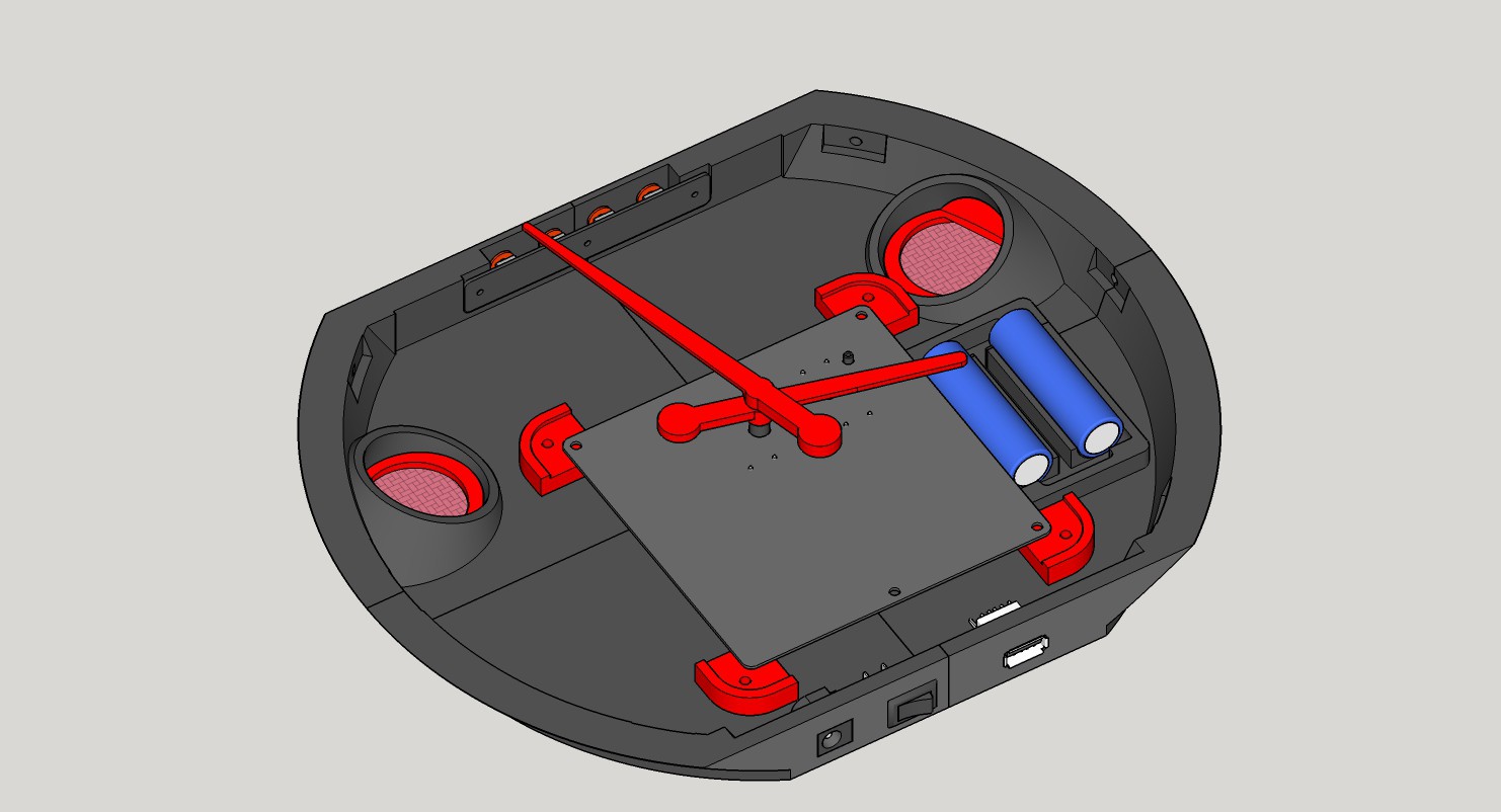
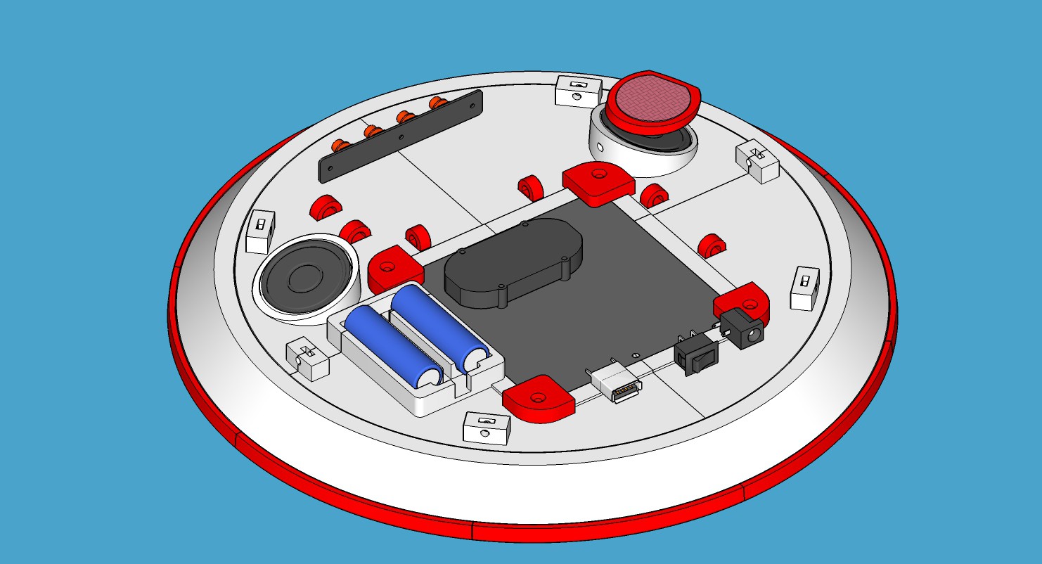
The clock runs from 2 Li+ Batteries (charging circuit present onboard) OR from and external 5V regulated supply. The batteries are connected in series or disconnected from the circuit and connected to a charging circuit, one for each battery.

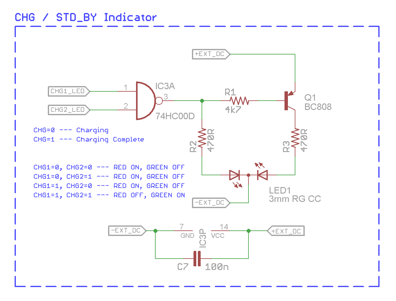
Since the batteries are being charge separately I used the next section of the circuit to detect when both are fully charged:
The audio part is based on a MP3 TF 16P module a pam8403 Amp IC, and 2 small 1W/ 8ohm speakers (LSM 36 M/B).

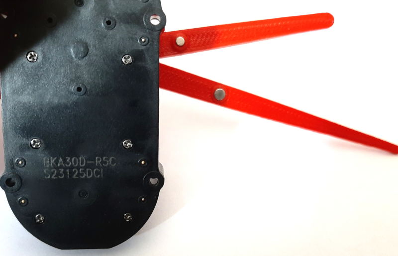
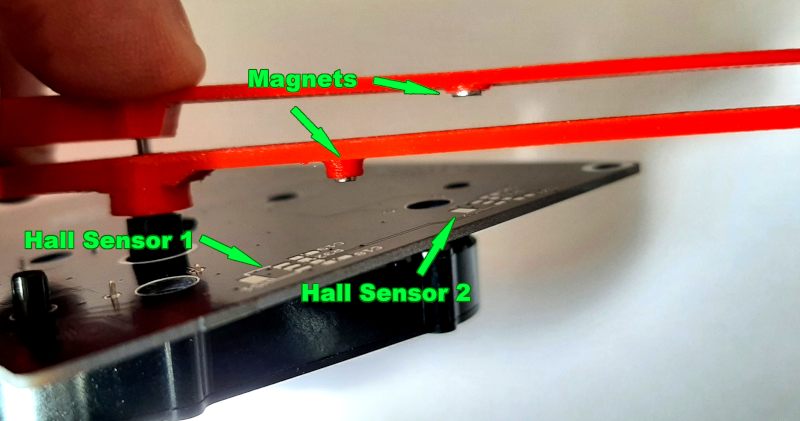
To calibrate the clocks arms position I used hall sensors (SS59ET) and small neodymium magnets placed on the minute and hour arms.
The calibration routine moves each arm till its sensor senses the most powerful mag field, reads the time from the RTC and then moves each arm to its position.
These are the magnets I used:
- Neodymium Magnet Ø3x1,5 mm NdFeB N52 (for the minute arm)
- Neodymium Magnet Ø2x1 mm NdFeB N52 (for the hour arm)
Every time a new hour begins the time is spoken by a female voice and then a bird sings for about 2 minutes. Between 10PM and 9AM the sound volume is automatically reduced. You can still hear it but it's very comforting instead of being loud.
To set the different operation modes, inquire the battery level, set the time, and so on, there are 4 manual buttons but also an HC12 module which receives commands wirelessly.
I also built a makeshift remote control on a piece of prototyping board, a temporary solution as I was rushing to finish it in time for Christmas.

3D Modelling the case
Everything was done in SketchUp.
I started with a rough sketch and work my way around the PCB and the Stepper's footprint.
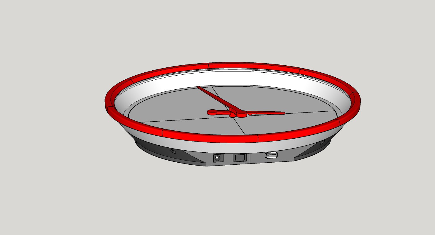
The finished clock measures approx. 290mm in diameter. And since my printer's capabilities are limited to 120mm x 120mm I had to split the main parts into 4 or 6 pieces, them printed them separately and then assembled together.
I took a little bit of cleaning / sanding to get a nice result but in the end I think it was worth it.
The Firmware
The AVR monitors the battery voltage, the RTC, communicates on its 2 HW UARTs with the HC12 Radio Module and the MP3 Audio Module, controls the audio amplifier (MUTE and StandBy) and drives the BKA 30d-R5 stepper.
I needed to write a few routines for the stepper, the RTC, and a library for the MP3 audio player. This module is a lot cheaper than something similar I've built have for the same purpose.
Mine is based on the VS1011 and since I've almost ran out of chips and they're much more expensive than this module, I've decided to give this module a try.
There are a lot o different documents for this modules and they're slightly different. Fortunately the UART communication is pretty straight forward. Once I got the checksum calculation and query working, the rest was piece of cake.
The firmware is in the files archive. The AVR's Fusebits should set like this:
Lockbits: FF
Fusebits: 7F
Fusebits High: D9
Fusebits Extended: FF
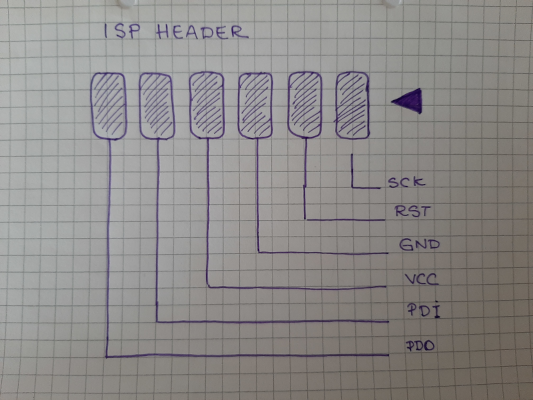
The pads for the ISP header are located below the AVR itself on the PCB:
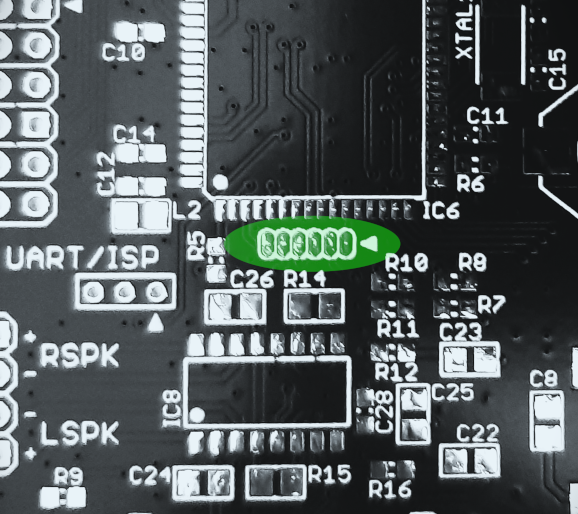
The UART/ISP Jumper must be set like this for programming:

If you wanna use the HC12 module to receive commands from a RC, after flashing...
Read more »
 Tobias Rathje
 Gary Marsh
 Hulk
Hulk
 Paul Kocyla