 max
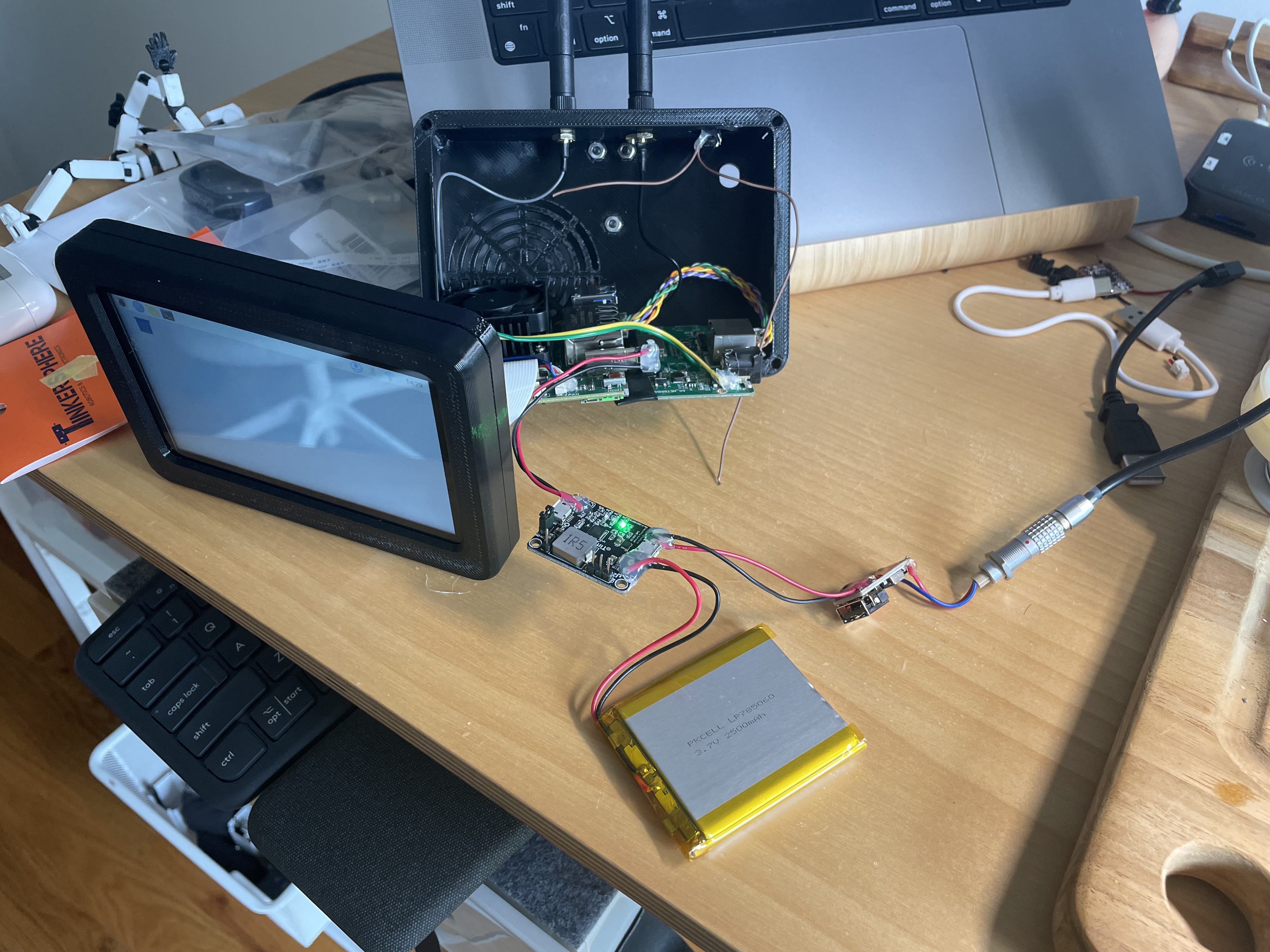
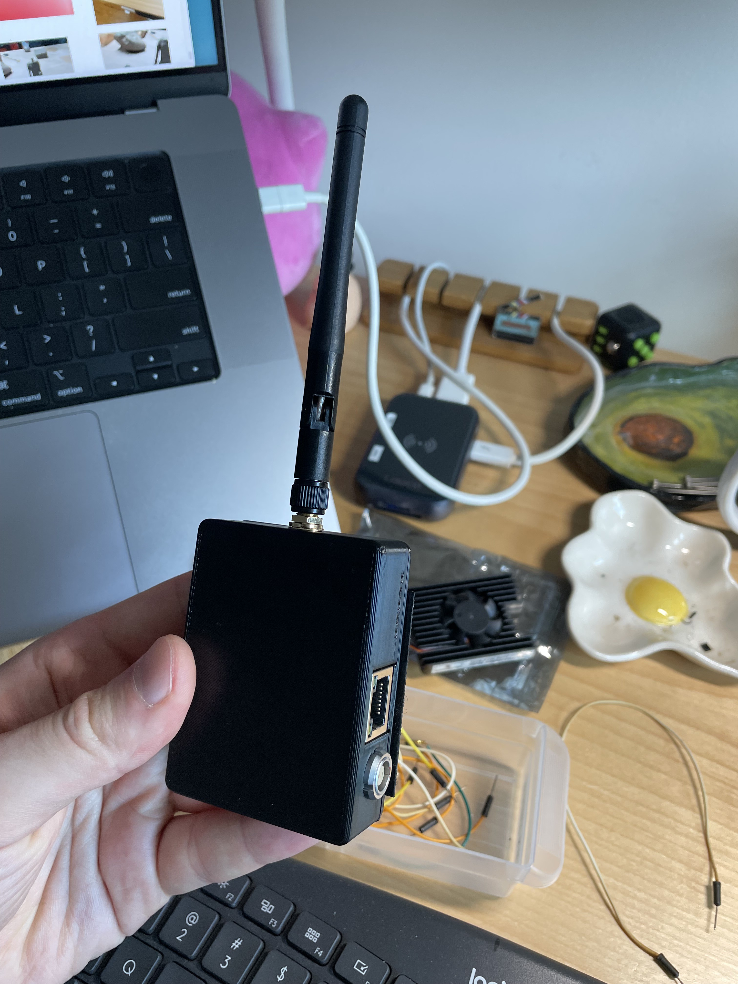
maxThis project is a Raspberry Pi CM4-based, portable, touchscreen computer for remotely controlling settings on modern cinema cameras. It utilizes 900mhz HaLow communication for wireless bridging, connected to the Ethernet port of whatever camera is in use. The goal is for it to be robust, slick, and professional-looking.
0%
0%
Camera Control Tablet
RPi-based cyberdeck tablet with a 900mhz WiFi HaLow radio built in
Become a Hackaday.io member
Already have an account? Log in.
Just one more thing
To make the experience fit your profile, pick a username and tell us what interests you.
Pick an awesome username
hackaday.io/
Your profile's URL: hackaday.io/username. Max 25 alphanumeric characters.
Pick a few interests
Projects that share your interests
People that share your interests
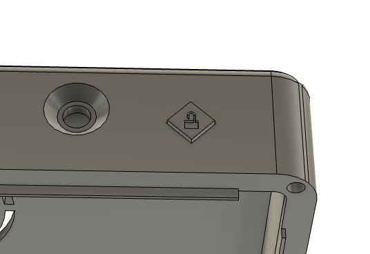
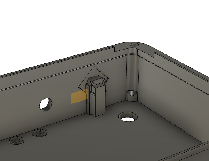

, Wedgie2 for mounting, and fan cutout")
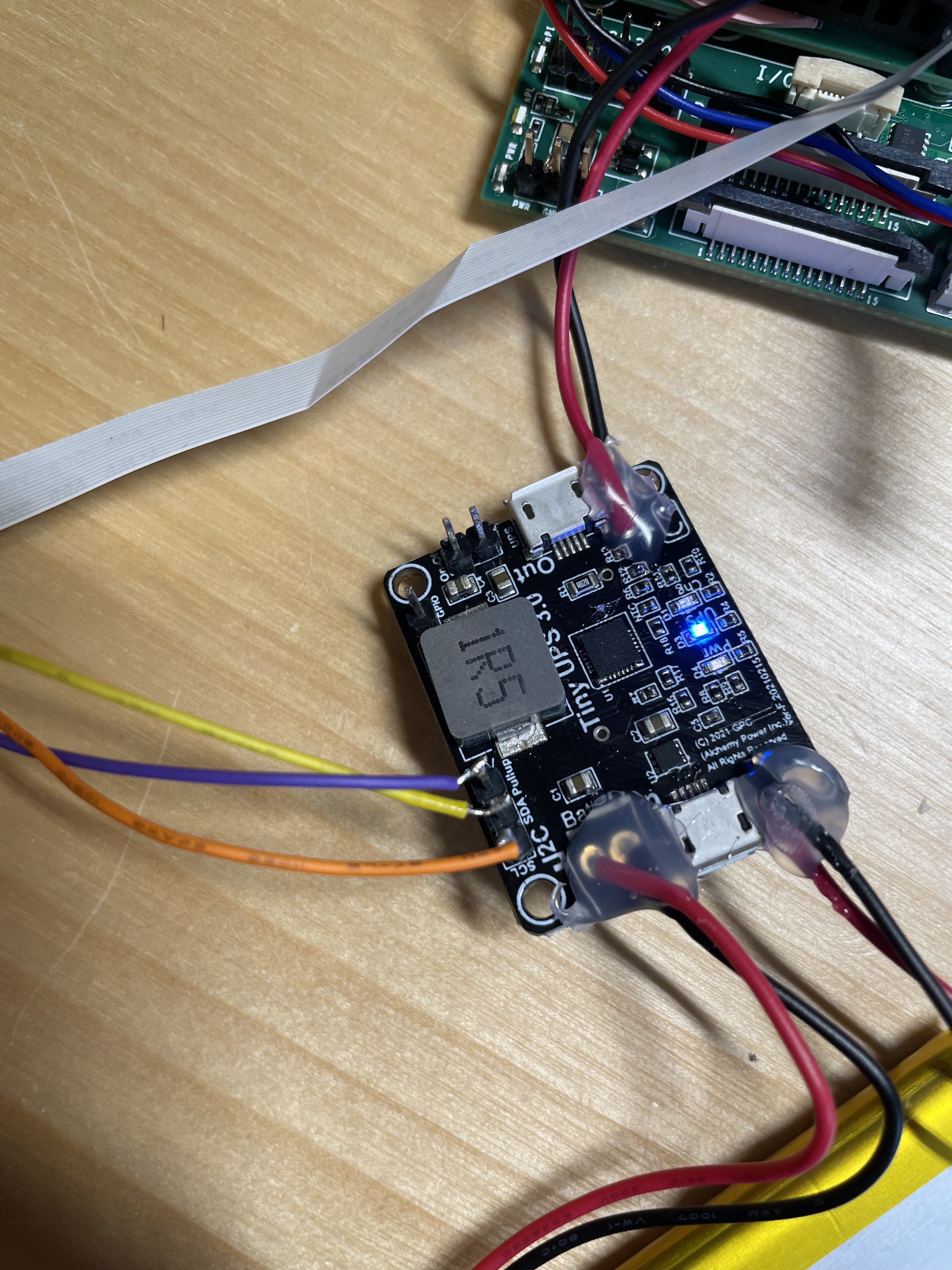
 and 900mhz, plus the power regulation")


 Jon Kunkee
 Dixbit
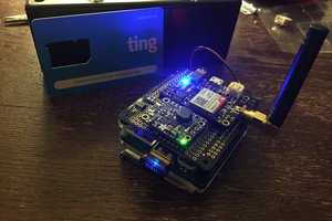
 fhlipZero
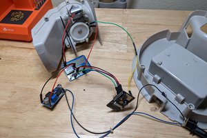
 Bradley Austin Davis