Close
0%
0%

Piper Arrow III Sim Cockpit

I‘m building an instrument panel of a Piper Arrow III for use with flight sims (X-plane in my case)

Public Chat
Similar projects worth following
I am trying to build a dashboard for a Piper Arrow III for use with flight simulators. The dashboard will be designed in such a way that it can be set up and taken down relatively quickly and easily on a desk (unfortunately, I do not have space in my apartment for a stationary, complete cockpit).
The dashboard will be built around a CH Products yoke (including rudder pedals) that I have owned for many years.

Why I‘m doing this?

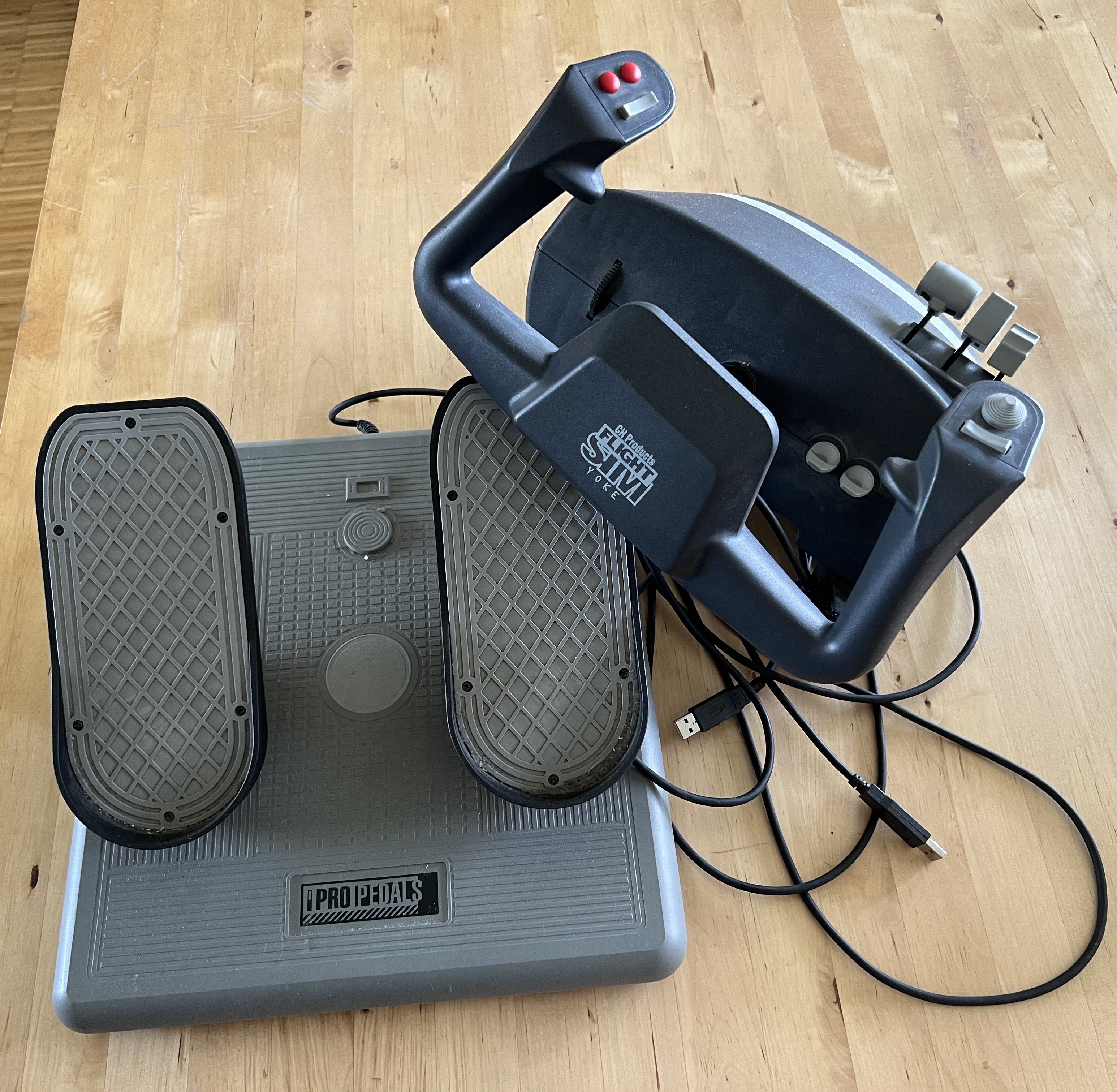
After many years of taking a break, I returned to my old hobby, "flight simulation," a few weeks ago. I found my over 20-year-old yoke and rudder pedals from CH Products in the basement and renewed my license for the latest version of X-Plane. After a few test flights, I noticed again what had always bothered me about flying with flight simulators: operating the flight instruments with a mouse on the screen.

Especially in “stressful situations,” it is extremely annoying to hit tiny controls with the mouse. It not only breaks the immersion when you suddenly have to tilt and scroll the viewing angle on the screen to look at some instrument, but often the slightest misclick means that complete settings in the GPS or transponder are reset or end up in completely different settings.

This is particularly annoying when using real-time ATC (e.g., through VATSIM) in the flight simulator, because not only do you frequently receive external instructions for navigation or radio communication, but you also no longer have the option to simply press the "Pause" button without ruining the simulation for all involved controllers and other sim pilots.

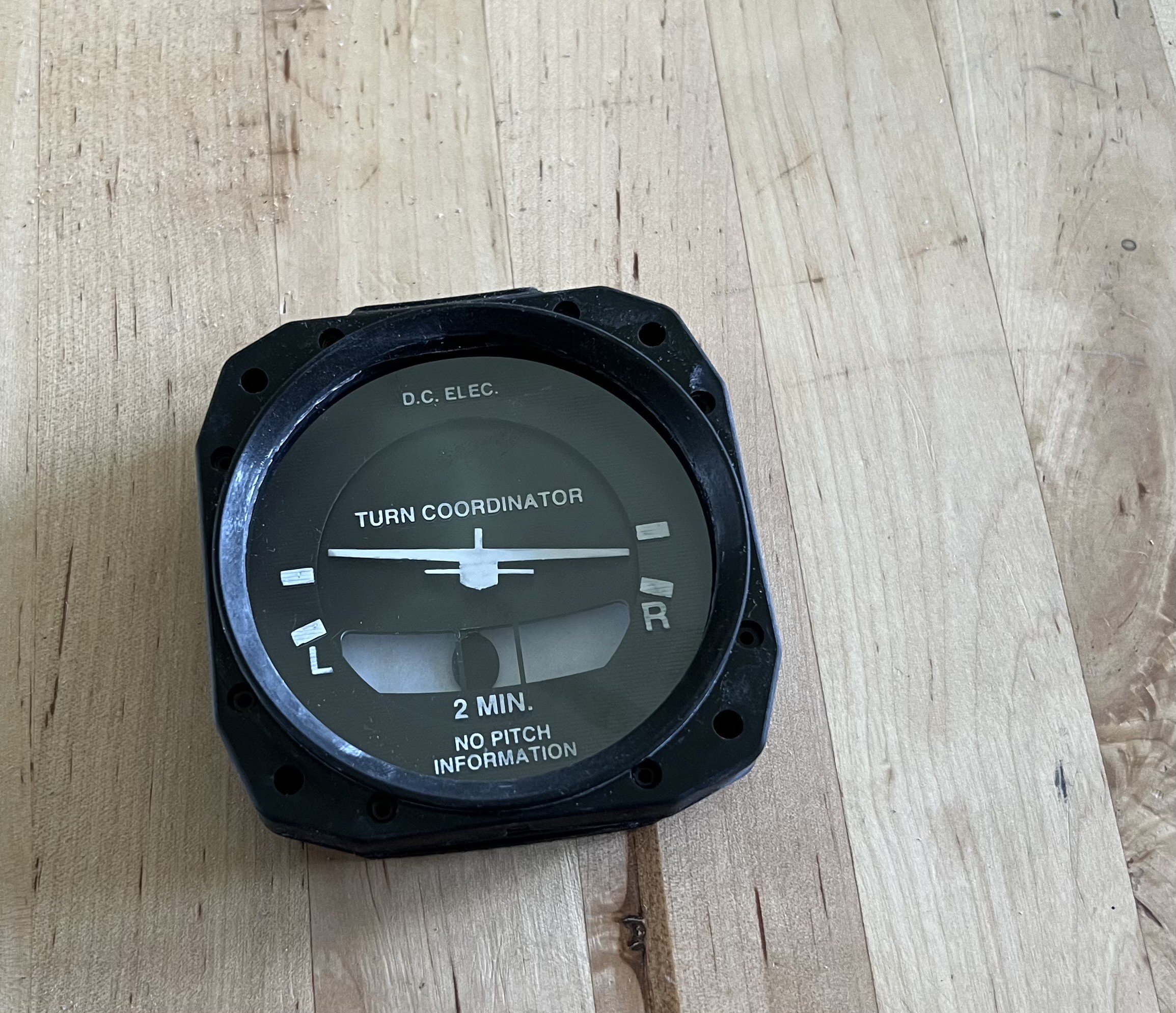
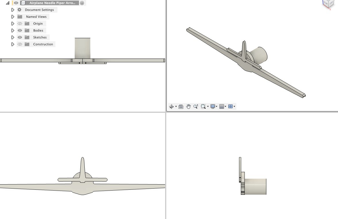
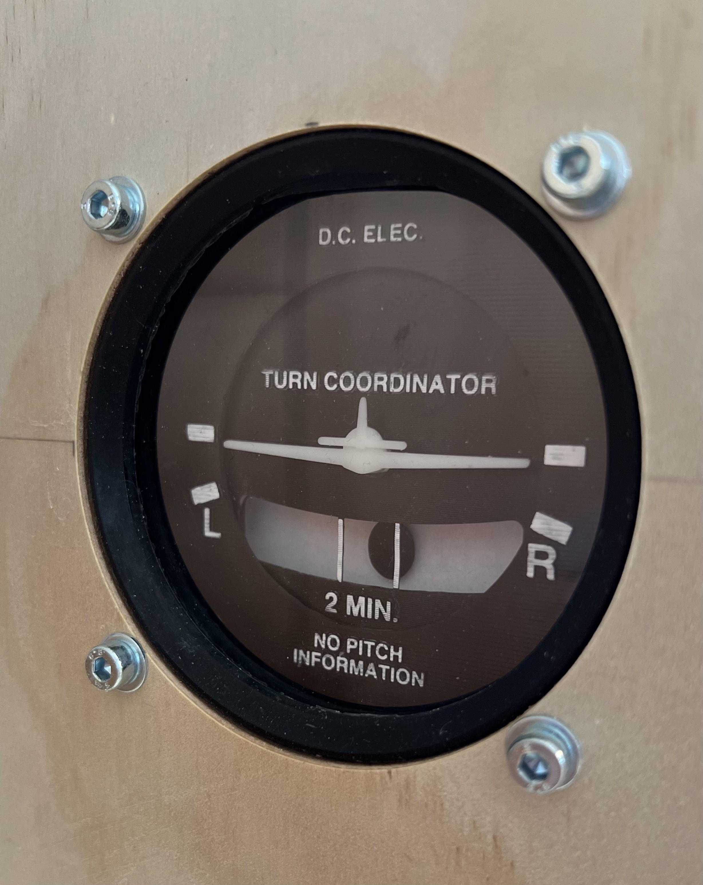
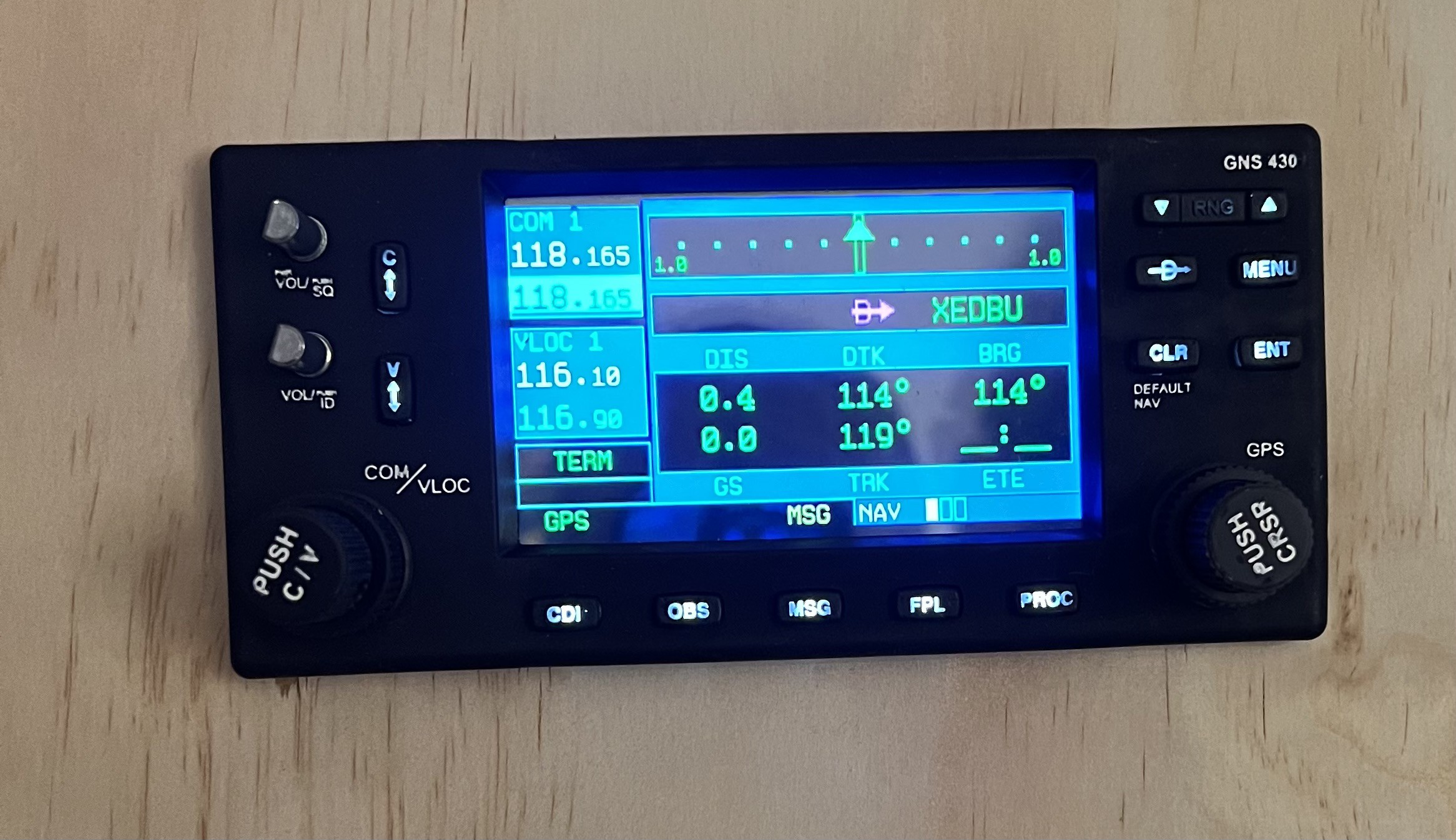
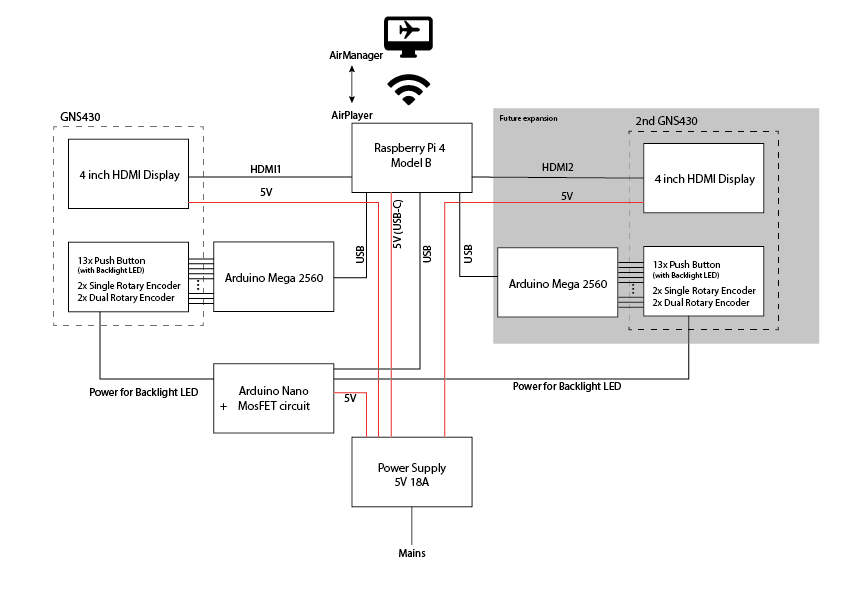
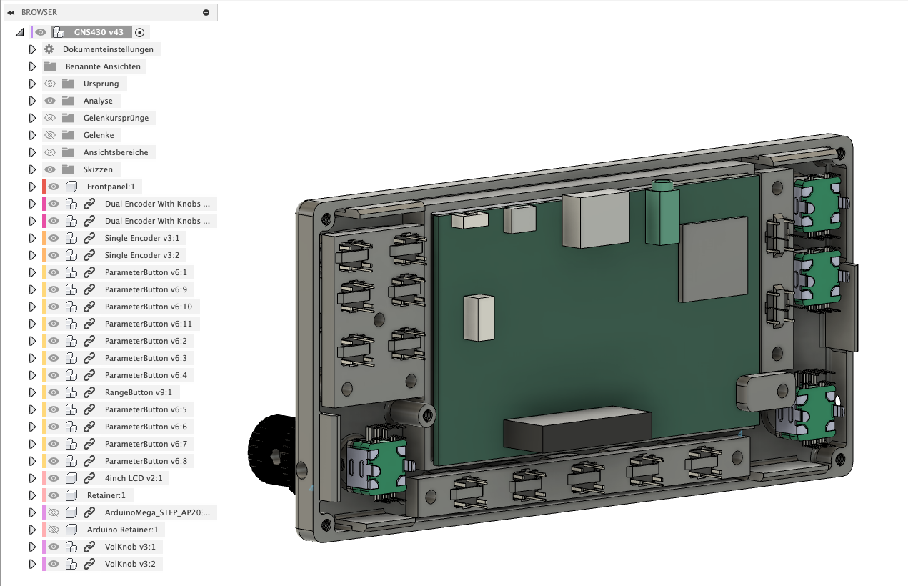
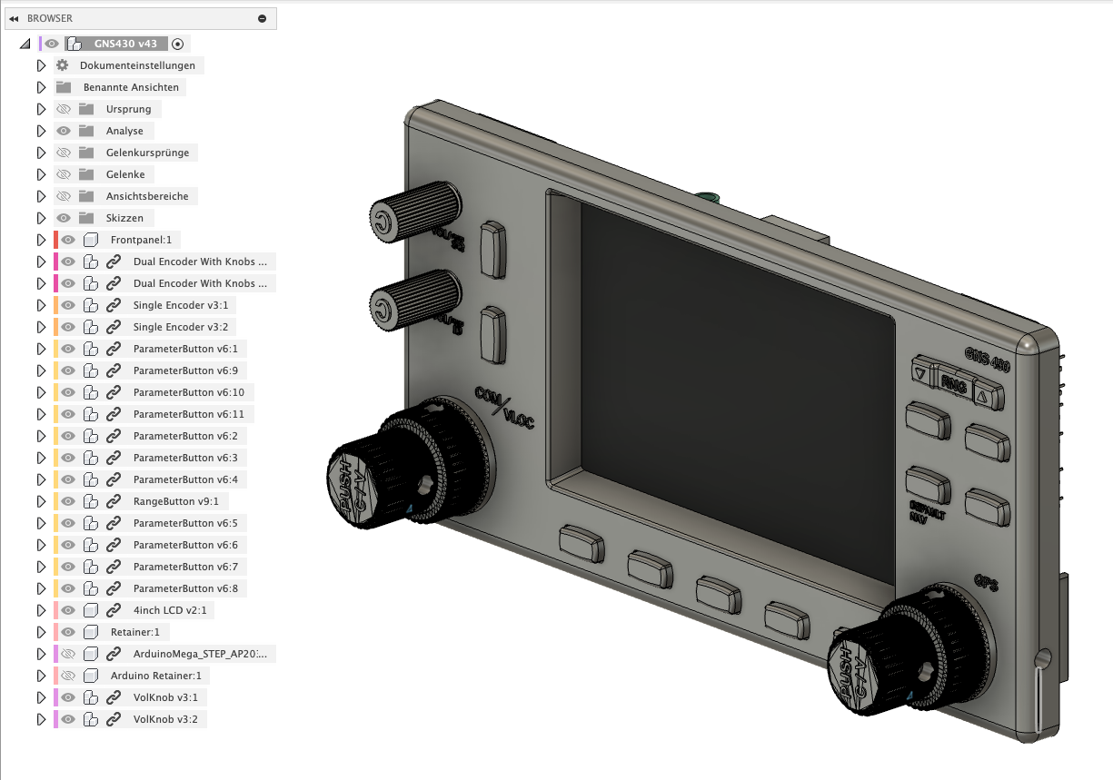
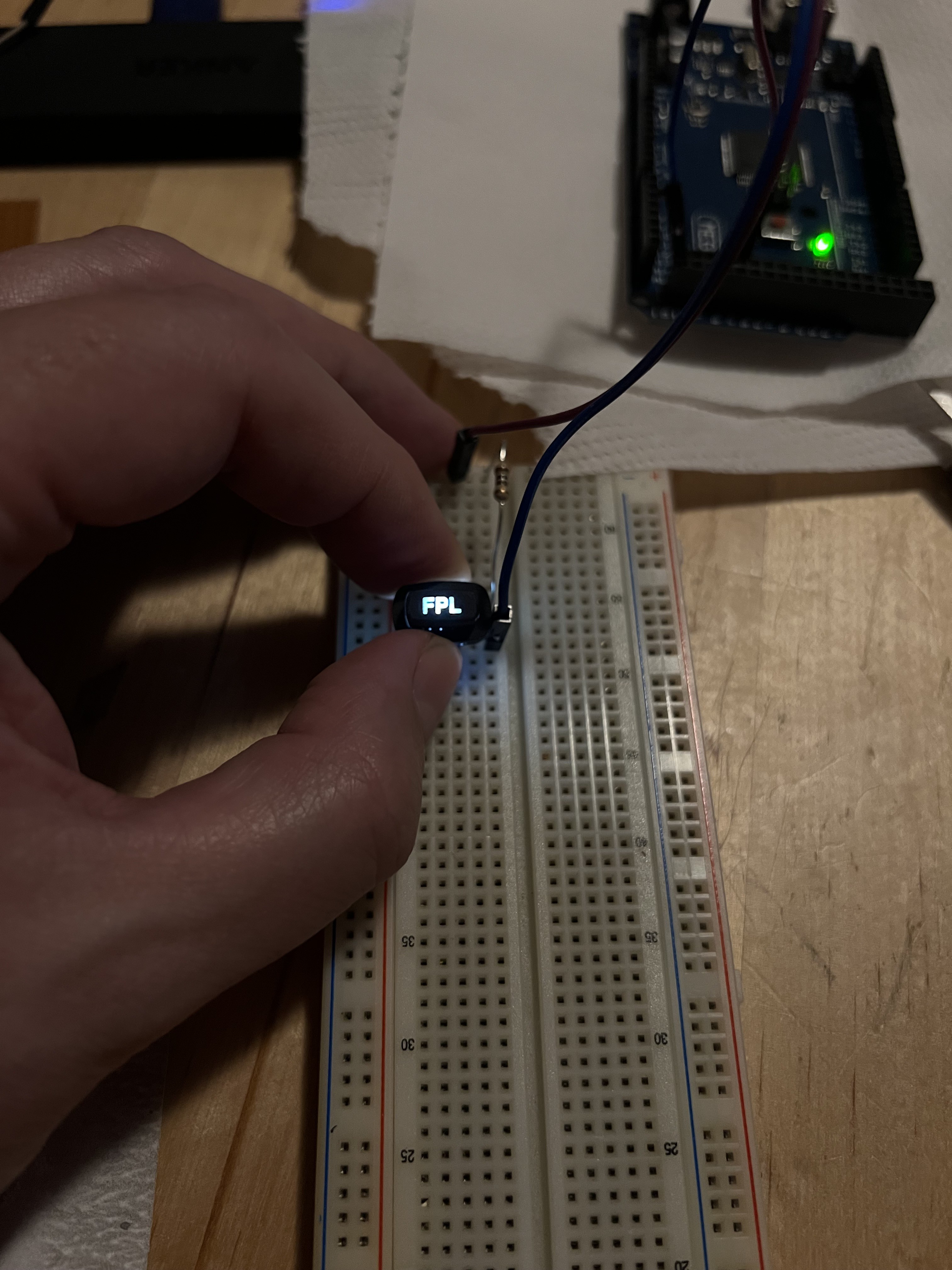
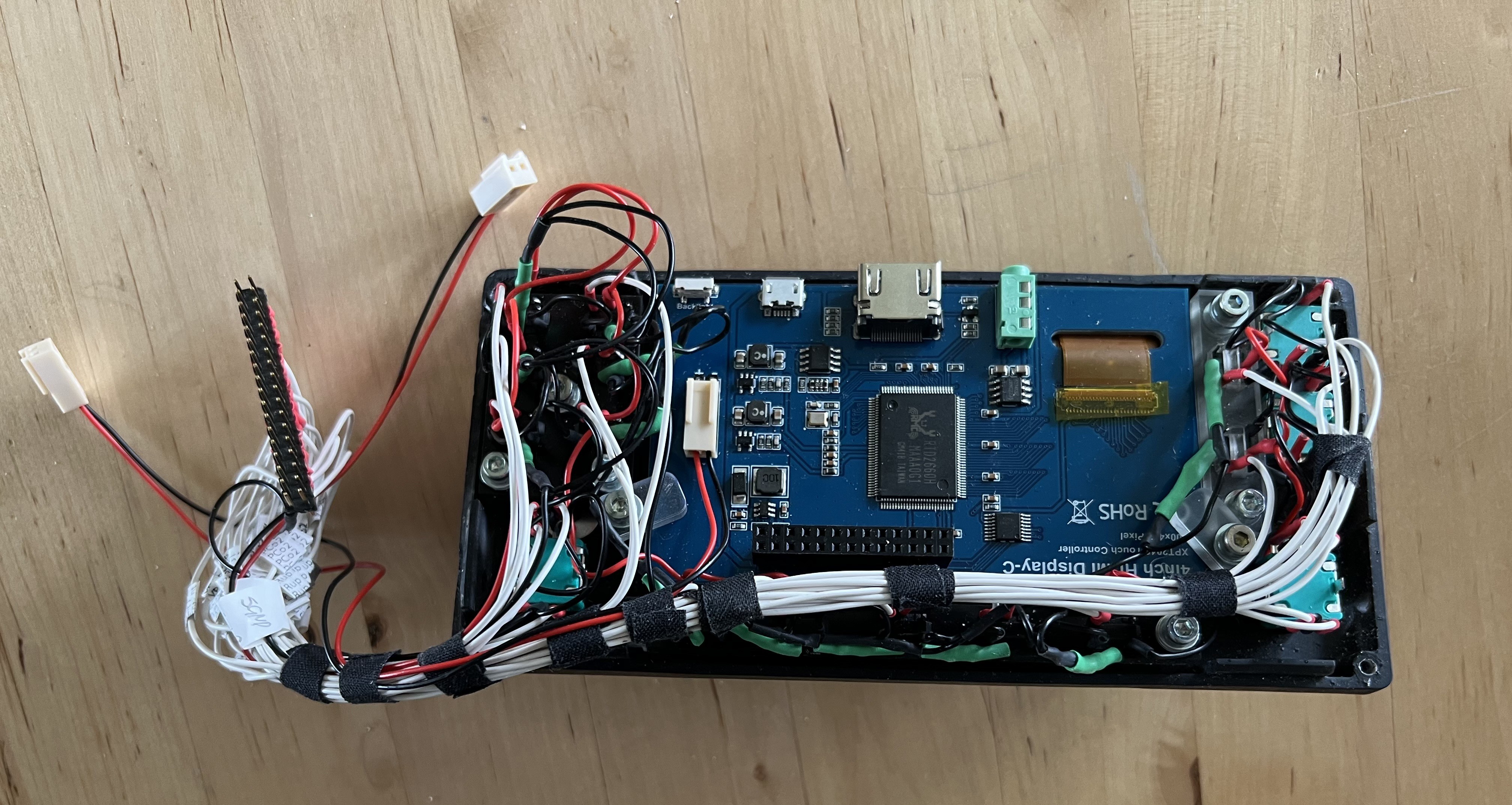
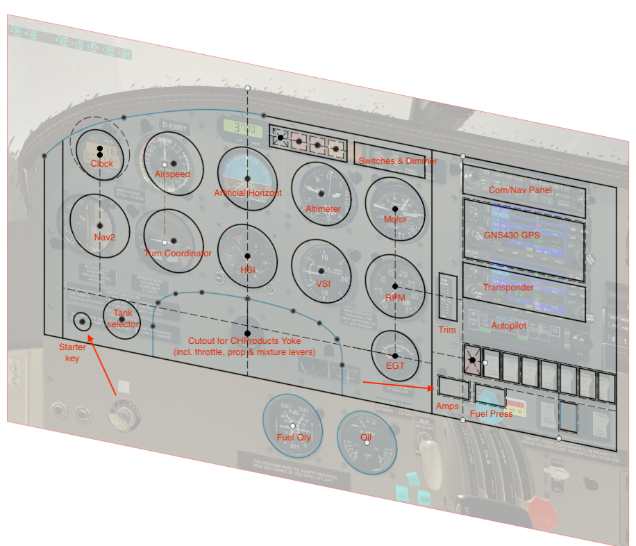
Therefore, my goal is to replicate the entire dashboard of a Piper Arrow III so that all instruments that function mechanically in the real airplane are also mechanically built in my dashboard. I'm not a fan of solutions where a monitor is simply placed behind a wooden board with appropriate cutouts. Of course, there are also "non-mechanical" devices in the cockpit, such as GPS. These will also have screens in my build, of course. Whether it's a mechanical or electronic instrument, the most important thing for me is that all the controls are mechanical. No virtual buttons or touchscreen elements.

  • 1 × CH Products FlightSim Yoke & Rudder Pedals
  • 1 × XPlane 12 Currently the Mac version
  • 1 × AirManager Software for connecting hardware (and software) instruments and controls to flight simulators
  • 1 × AirPlayer Companion app for AirManager, running on a Rasperry Pi
  • 1 × Raspberry Pi 4

View all 7 components

  • Turn Coordinator

    Zaggo5 天前 0 comments

    After finishing the GNS 430 installation, I moved on to the analog instruments of the dashboard.

    A great source of inspiration, as well as Fusion 360 designs, is Captain Bob's YouTube channel, which features a variety of aviation-related projects. Inspired by his content, I decided to try his design for a Turn Coordinator. I used his design almost unchanged; however, I applied the same technique for the text and graphics on the instrument that I also used in the GNS 430 build: instead of using stickers, I embossed the text and lines directly onto the 3D-printed faceplate and then painted them white with a paint pen:

    Although Captain Bob's design was intended for FDM printers, I had no trouble adapting it for my resin printer. Additionally, since I don't own a laser cutter, the clear screen is not a laser-cut piece of acrylic glass as originally designed, but rather a simple overhead transparency sheet cut with my trusty eight-year-old Silhouette Portrait cutter. It looks surprisingly convincing and also serves as dust protection for the instrument.

    After a first dry fit, I decided to redesign the little airplane needle, as Captain Bob’s version is tailored for a Cessna 172, whereas I am building a dashboard for a Piper Arrow III. Using close-up screenshots from my flight simulator as a reference, I designed this alternative instrument needle in Fusion:

    If someone is interested, here's the Fusion file: https://bitbucket.org/zaggo/pa-28-dashboard

    And here's the final design:

    The instrument is powered by two X27-168 stepper motors, one driving the airplane needle (turn rate) and the other controlling the "ball" (slip rate). Unfortunately, I encountered issues when trying to drive these motors directly from AirManager, even though these motors are used in their example code for driving stepper motors. After discussing this in their forums, I received a suggestion to reduce the motor speed in the code, which kind of worked. However, the motion of the needles was still quite jerky and slow, which I found unsatisfactory. During this process, I also experimented with controlling the motors using an Arduino sketch and the SwitecX25 library. This approach worked immediately and was significantly smoother than the jerky AirManager driver.

    Fortunately, AirManager also offers a library for Arduino, SiMessagePort, which facilitates communication between AirManager and any Arduino sketches. Therefore, I decided to integrate an additional dedicated "Stepper Driver" Arduino into my build.

    Here's the current simple sketch for driving the X27 motors based on commands sent via the SiMessagePort by AirManager:

    #include <SwitecX25.h>
    #include <si_message_port.hpp>
    
    // standard X25.168 range 315 degrees at 1/3 degree steps
    #define STEPS (315*3)
    
    SiMessagePort* messagePort;
    
    // For motors connected to digital pins 4,5,6,7
    SwitecX25 motor1(STEPS,4,5,6,7);
    SwitecX25 motor2(STEPS,8,9,10,11);
    
    static void new_message_callback(uint16_t message_id, struct SiMessagePortPayload* payload) {
      if (payload == NULL) { return; }
      if (payload->type != SI_MESSAGE_PORT_DATA_TYPE_FLOAT) { return; }
      float relPos = payload->data_float[0];
      messagePort->DebugMessage(SI_MESSAGE_PORT_LOG_LEVEL_INFO, (String)"Received position: "+relPos+" for motor: "+message_id);
      switch(message_id) {
        case 1: 
          motor1.setPosition(relPos * STEPS);
          break;
        case 2:
          motor2.setPosition(relPos * STEPS);
          break;
      }
    }
    
    void setup(void)
    {
      // Init library on channel A and Arduino type MEGA 2560
      messagePort = new SiMessagePort(SI_MESSAGE_PORT_DEVICE_ARDUINO_MEGA_2560, SI_MESSAGE_PORT_CHANNEL_P, new_message_callback);
     
      // run the motor against the stops
      motor1.zero();
      motor2.zero();
    
      // start moving towards the center of the range
      motor1.setPosition(0);
      motor2.setPosition(0);
    
      messagePort->DebugMessage(SI_MESSAGE_PORT_LOG_LEVEL_INFO, (String)"Servos zeroed and driver ready");
    }
    
    void loop(void)
    {
      messagePort->Tick();
      // the motor only moves when you call update...
    Read more »

  • The GNS 430 GPS

    Zaggo05/01/2024 at 11:46 0 comments

    The first device I built was the GNS 430 GPS unit. Here's the finished thing:

    I wanted this to have with backlit buttons and real dual rotary encoders. After searching the web for a while it became clear, that I had to design this myself.

    The screen content comes directly from the flight sim. But since I'm currently running the sim on a Macbook Pro, and thus do not have an option to connect too many external displays, I use AirManager for grabbing the GPS' display content directly from XPlane and sending it via a network connection to a Raspberry Pi 4. This works surprisingly well, even over wifi. Unfortunately the Raspberry doesn't have enough GPIO pins to also drive all the buttons and encoders. I originally planned to build two GNS 430 units anyway (as there are two of them in the simulator) and it's no problem for the Raspberry Pi 4 with its 2 HDMI connectors (and the AirManager/AirPlayer combo) to provide the display content for both of them. So I decided to use a separate Arduino Mega 2560 for interfacing with all the hardware buttons and encoders. To my pleasant surprise, it's even possible to connect the Arduino(s) directly to the Rasperry Pi and setup AirManager/AirPlayer in such a way, that all information is transported via the netrwork connection. This greatly reduces the need for cables between the dashboard and the computer. In fact, there is actually 0 (zero) cables between the main computer and the dashboard, since everything is working great so far with just a WiFi connection between the Mac and the Raspberry Pi. The only cable going to the dashboard is a power cable!

    Here's the current wiring schematic of the GNS 430:

    I did draw the whole design in Fusion. I was able to use some parts (like the rotary encoders) from GrabCAD, but most parts (including the backlit push buttons and the LCD) I drew myself.

    After a few failed test prints of the tiny push button covers with my > 10 years old LulzBot TAZ 6 it was clear, that a FDM printer wouldn't cut it (at least mine). So after more than 15 years of FDM printing, I decided that it would be time to give resin printers a try and bought a Elegoo Mars 3 Pro.

    Using a resin printer after years and years of FDM printing is maybe a story for a different time, but I finally managed do successfully print first push buttons!

    I printed these with clear resin and airbrushed them black afterwards. Finally I sanded off the black coating from the embossed text and voila: A backlit push button:

    I ordered most of the hardware for cheap from Ali Express (rotary encoders and a bag of 100 pcs "6x6x7mm through hole reset micro push button tactile momentary switch with led (white)"), and a 4 inch IPS display with HDMI port from Amazon (not so cheap).

    The white text on the frontpanel and the encoder knobs is also 3D printed, embossed text. But this time the part was printed with black resin and the embossed text later painted white (with a white paint pen).

    And here's the thing, all cabled up, after assembly:

    On the software side, I wrote a LUA script for my GNS 430 in AirManager (I'm new to AirManager and also LUA, so please let me know if I can optimize the code!).

    The LCD-Content is fetched from XPlane and send to the AirPlayer instance on the Raspberry Pi with this simple command:

    video_stream_id = video_stream_add("xpl/GNS430_1", 0, 0, 800, 480)

    All the buttons and encoders are then mapped by a script, running on the Arduino Mega:

    ------------------
    -- GPS PushButtons
    ------------------
    
    cvol_event = 0
    
    function cvol_pressed()
      print("cvol_pressed")
      xpl_command("sim/GPS/g430n1_cvol", "BEGIN")
      
      local event = cvol_event
      timer_start(2000, function(count)
        if event == cvol_event then
            print("Shutdown")
            shut_down("SYSTEM") 
        end
      end)
    end
    
    function cvol_released()
       cvol_event = cvol_event + 1
       -- print("cvol_released, cvol_down is now "..cvol_down)
       xpl_command("sim/GPS/g430n1_cvol", "END")
    end
    
    hw_button_add("CVol", cvol_pressed, cvol_released)
    ...
    Read more »

  • What am I doing?

    Zaggo05/01/2024 at 09:54 0 comments

    Well, here's a screenshot of a Piper Arrow III Dashboard in X-Plane:

    And I try to build most of it.

    As said before: I already own a Yoke and Rudder pedals, which are fine and I currently do not intent to build these from scratch. 

    This might be different if I'd plan to build a full cockpit, but unfortunately there's no space for this in my apartment. So a desktop cockpit it'll be and the existing yoke with its table top screw clamps works great for this use case.

    So, based on the above screenshot and the existing hardware, I came up with this layout:

    So most instruments will be in their original place. Some components needed to move, since my dashboard will end on the tabletop. So, for example, I moved the starter key slightly from it's position slightly "under the tabletop" to a free space above. Same thing for the fuel tank selector, which is originally located down by the knee of the pilot, on the left wall of the cockpit, to a free space next to the starter key (I also sized it down). 

    I don't have to build the throttle, prop and mixture levers, since these are part of the existing yoke assembly.  But I had to move the alternator amp and fuel pressure gauges out of the way for the yoke cutout.

    There's no space for the fuel and oil pressure/temp gauges, which are originally also below the "tabletop line". I'll figure something out later...

    All the switches for the lights and avionics will be more or less in their original spots. 

    And I'll fill the stack of electronics above the switches (like GPS, Transponder, Autopilot etc.) dynamically as I build them. They should have all more or less the same width, which means, that I can rearrange them as needed in a large rectangular cutout (like in the real dashboard).

    The backplate will be out of 5mm plywood, somehow fixed to the yoke and/or tabletop, so everything will be easily setup in a few minutes. However, the exact structural framework is yet unclear for now.

View all 3 project logs

Enjoy this project?

Share

Discussions

Similar Projects

Does this project spark your interest?

Become a member to follow this project and never miss any updates