 ogdento
INTRO
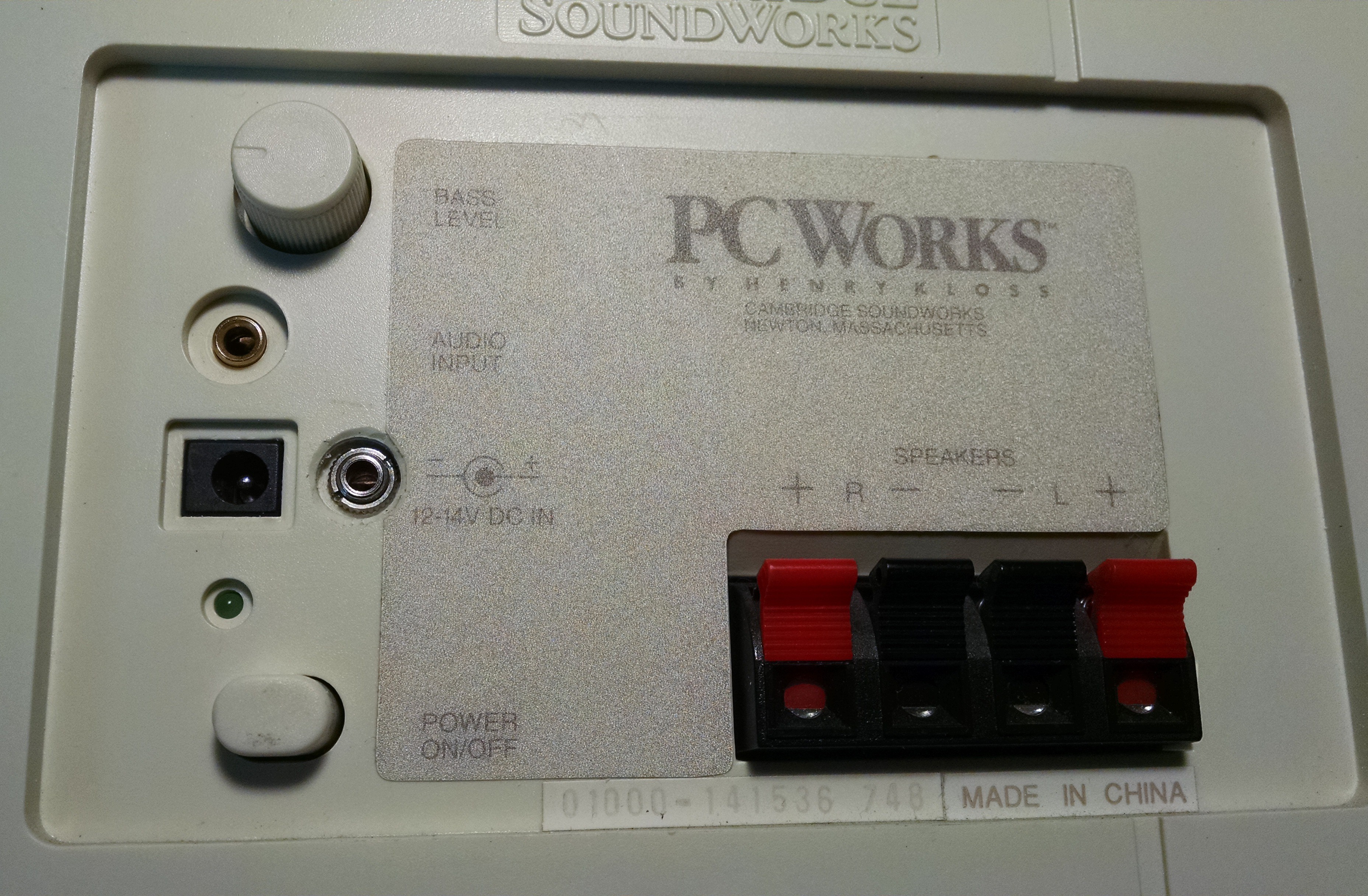
The PC Works speaker system was originally 35 bucks around 15 years ago, and it still sounds great in my opionion. It's certainly not an audiophile setup but like I said, it was 35 bucks. I have two of these systems - one is connected to my tv and the other is used on a raspberry pi running Volumio and shairport.
This hack will work on a PC Works speaker system that uses the TDA1554Q amplifier chip. The TDA1554Q replaced the OM8384J chips that were in older versions - I can't find a spec on the older chip so I do not know if it has the same mute pin. So do this hack only on a TDA1554Q system!
THEORY
A quick look at the TDA1554Q spec showed that Von is >= 8.5v and that Vmute is 3.3 to 6.4v. There are two boards inside the subwoofer of this system - one board is an audio input board, and the other is the main amplifier board. A little probing around the two boards uncovered both a 5v and 12v source. I built the following PNP transistor circuit so that a 5v signal from the raspberry pi will turn ON the amp, and a 0V signal will turn OFF the amp:

The mute input of the TDA1554Q is at pin 14. There are two supply voltages in the circuit - one is a 12 volt supply which is available on the audio input board, and the other is a 5 volt supply which is tapped from a regulator on the main amplifier board.
A 1/8" control plug is used to signal the amp to be muted or not. When the control plug is disconnected, 5v is supplied through the jack and the PNP transistor is kept ON, providing enough voltage across R2 to keep the amp ON. When the plug is connected, 0v will turn the transistor OFF (muting the amp) while 5v will again leave the amp running.
CONSTRUCTION
Getting this thing together was not too difficult but it did require a dremel a razor and some drill bits. The hardest part was cramming the jack into the subwoofer case and bringing the voltage and signal lines to the jack and the transistor circuit (which was simply soldered right onto the jack). The main amplifier did require some circuit trace modifications, as shown below:
Again, the mute pin is pin 14 on the TDA1554Q. It is connected to a positive supply voltage on the circuit board. I needed to cut the traces to isolate pin 14, and then make sure that the other bits of the circuit still got the required supply voltage after I made my cuts.

In the above picture, the Purple arrow shows the location of pin 14. I made cuts at the Yellow and Orange circles to isolate pin 14. I also drilled a small hole at the Yellow circle so I could attach a wire to the pin 14 trace (I guess I could have soldered right onto the pin, but the wire was coming from the top-side of the board). Finally, I had to add the small red jumper to re-connect the rest of the circuit that was isolated by my cuts.
The transistor circuit was built with an A1015 PNP transistor because that's what I grabbed out of my parts bin. It can handle 150ma which is more than enough for the mute input. I soldered the resistors and transistor directly onto the 1/8" jack that would be housed with the audio input board. I brought two wires - a red one for the 5v supply and a yellow one for the pin14 input - from the main amp board, and picked up a 12v supply and ground from the audio input board, as seen below:

A close up of the transistor circuit is shown below:
 I did drill a small hole through the audio input board to solder on the 12v supply wire, but there was already a hole I could use to solder in the GND wire. I also had to make a notch in the plastic housing of the audio input board to pass the red and yellow wires through.
The 1/8 jack (silver jack to the right of power input) was mounted very near to the audio input (gold jack above the power input), which was actually not the best choice... since it's the same size as the audio input jack I have to be extra careful what cables I plug where!
OPERATION
Getting this thing to work with the raspberry pi required some scripts to turn on the GPIO port when the music started, and turn it...
Read more »
 Electroniclovers123
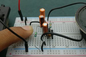
 engineerkid1
 Todd
Todd
 Jon
Jon