 Ayu
Ayu🎛️ Controls
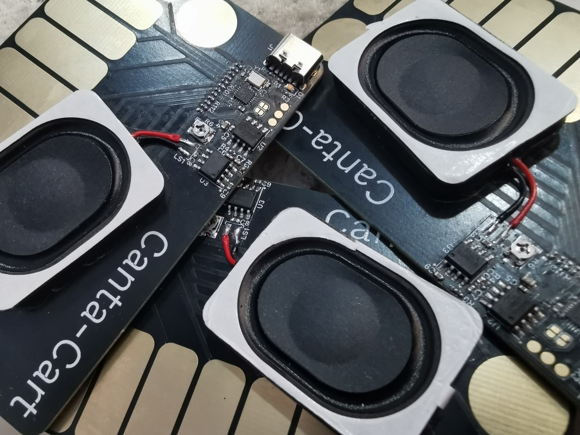
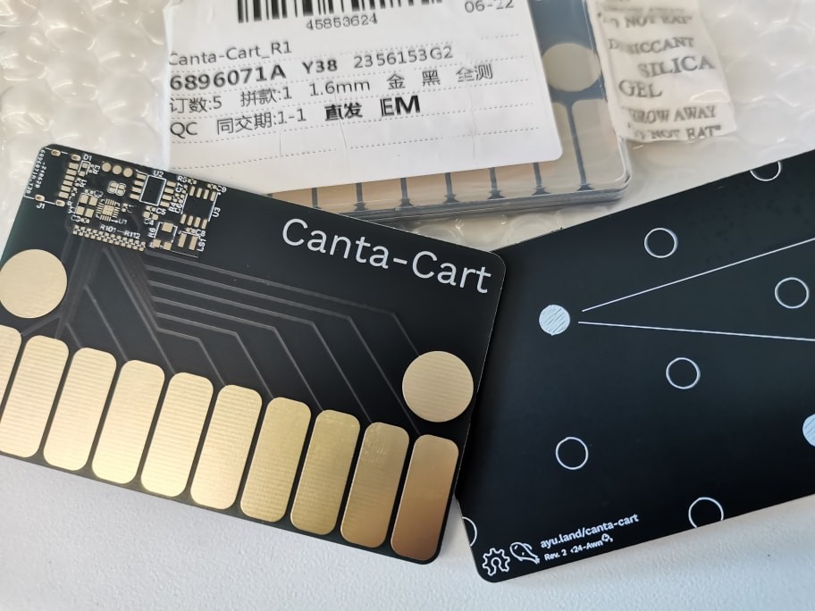
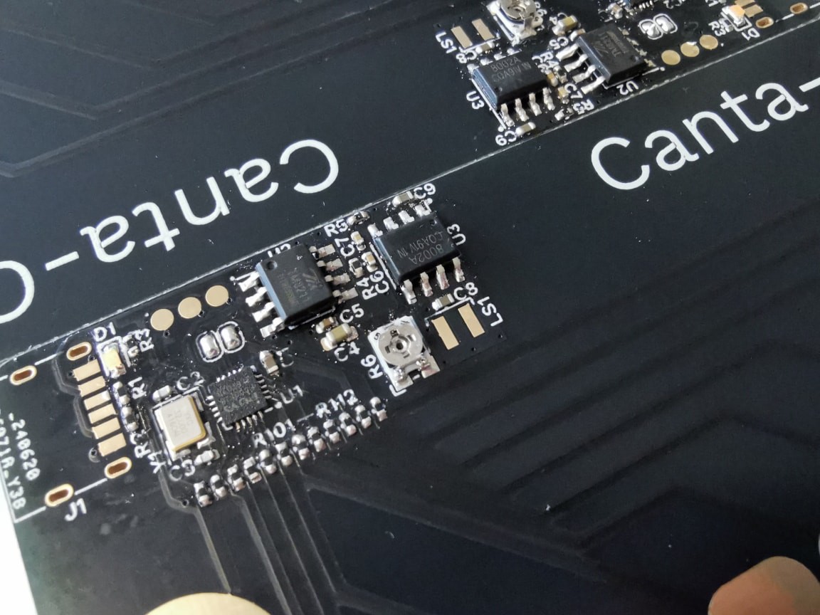
On the card are 12 touch keys (10 for sounds, 2 for transposition). The sounding keys correspond to the pitches in a diatonic major scale, spanning a tenth interval.

The transpose buttons open up to a variety of ways to extend this. They work as follows:
- Press once: move along the scale.
- Hold and play a note: accidentals.
- Press one while holding the other: key change.
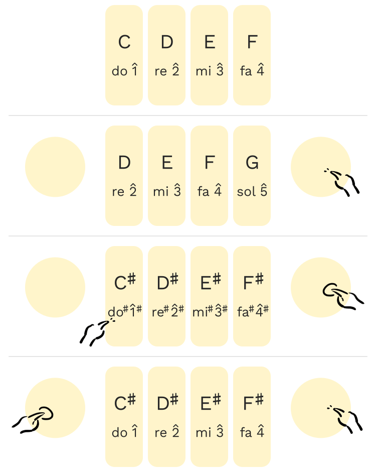
The rationale is that most melodies (in music cultures compatible with the Western tonal theory) span a pitch range of around a tenth, at least over short periods, due to the register of the human voice and how musical instruments and compositions tend to imitate and invoke it. Thus, ten keys are mostly sufficient for a player to reproduce most melodies. The transpose buttons open a way to pitches beyond the ten-note major scale in cases where they are needed, covering the remaining cases as well as providing abundant chances for harmonies, musical textures, etc., through which delicate musical expression becomes more than possible.
⚙️ Inner Workings
(Please refer to the firmware source for all details.)
Capacitive Sensing
Touch sensing is achieved by utilising the step response of an RC network.
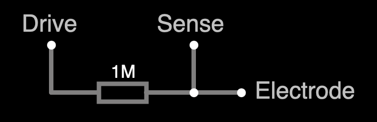
The circuit consists of a large resistor (~1 MΩ) in series with the sensing electrode. The latter can be treated as a capacitor to the circuit’s ground (not necessarily earth; a battery negative reference works just fine), whose value increases as human body parts approach it. A driving pin feeds the network with a step signal (namely, drives it high) and monitors the voltage change across the resistor, waiting for the sensing pin to go “logical high”. As the step response of this network is an exponential function (the derivation of which is explained in any basic electronics textbook), for the voltage at the sensing point to rise above the logical high threshold V_IH = k · V_CC (with a typical value of k = 0.7), the time taken is -ln (1 - k) · RC which is linearly dependent on the sensed capacitance C. By repeatedly sampling GPIO pins, the capacitance values at all electrodes can be straightforwardly deduced.
Run a simulation of the circuit here.
Audio Synthesis
The synthesiser is a basic triangle wavetable synth combined with an attack/release envelope. All calculations are carried out with 32-bit integers, minimising the time spent in synthesis and reducing overall latency to under 1 ms.
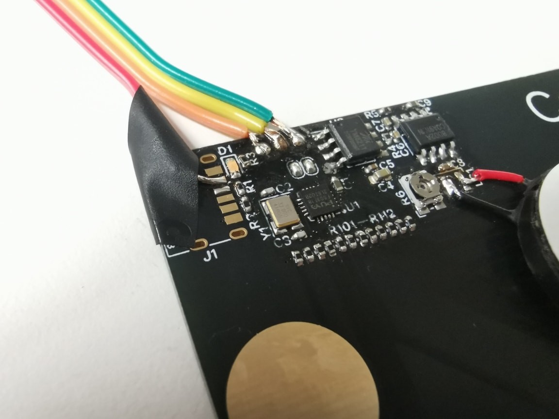
Audio Output
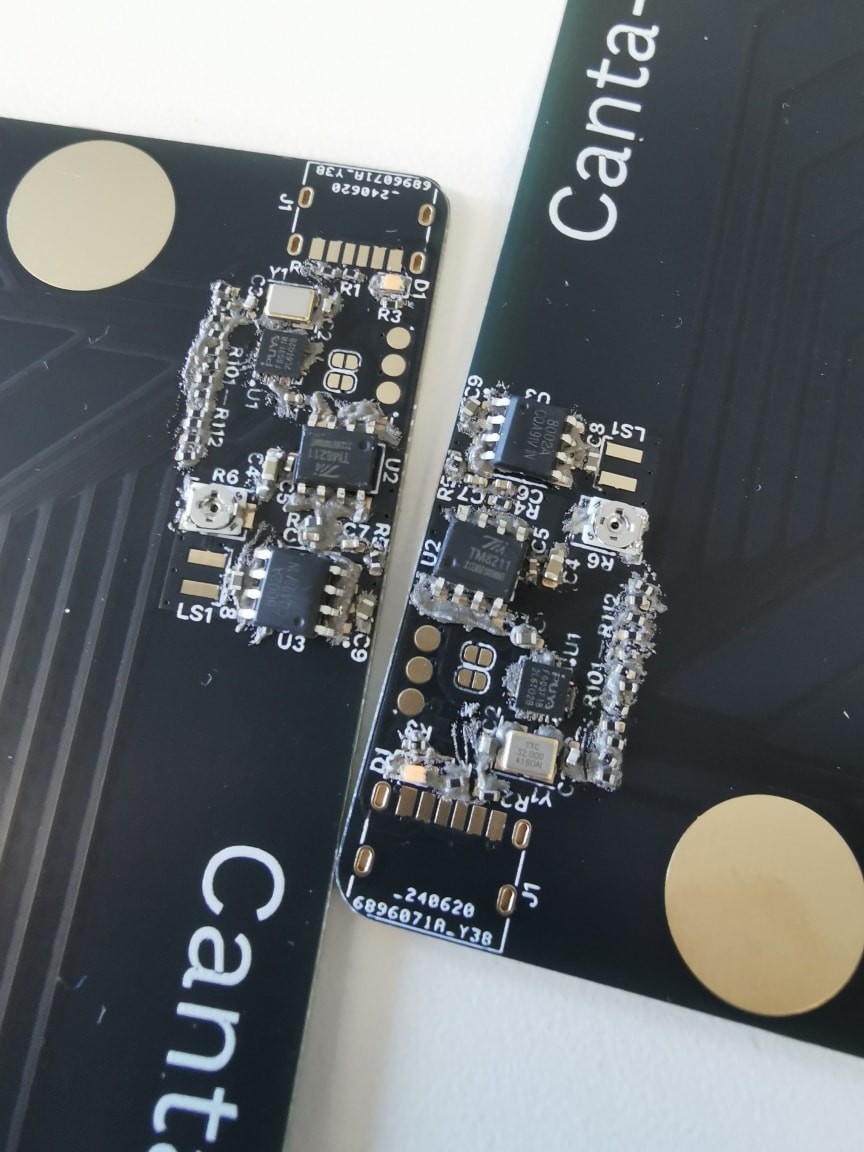
Audio is sent to a DAC through a digital bus comprising three signals: word select (WS), bit clock (BCK), and serial data (DATA). The DAC IC in the circuit expects the LSBJ format, which closely resembles the standard I²S. Our microcontroller does not have a ready-to-go peripheral for such formats, but it is possible to work within the limitation: BCK and DATA can be covered by an SPI output, and WS can be supplied by a carefully synchronised PWM timer channel. The DMA provides a half-complete interrupt, easing the implementation of a double buffer.
Why do these strange limitations arise? To squeeze out every penny/cent, of course! Which leads us to…
🔥 The Muntz Wildcard
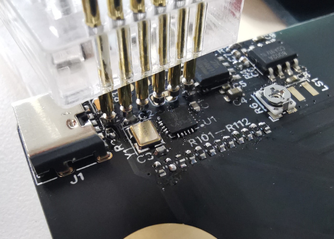
Cost-effectiveness was an overarching consideration in the design. This gave rise to a few absurdities in the implementation, but as things were pieced together, they amounted to a knockdown BOM cost of US$0.6 per unit. As quite a few PCB houses now provide free prototyping services for boards of this size, this is the final manufacturing cost of the device. (Components can all be manually soldered with a hot air gun or an iron; I’m by no means a seasoned maker as electronics is only my side research as a design-focused student, but I did it all simply with solder paste and a hot air gun, without a paste stencil, a magnifying glass, or solder flux. YMMV, though.)
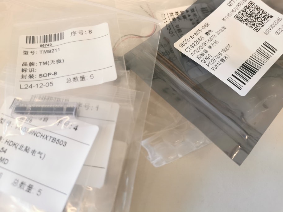
The microcontroller is at the heart of the device and often a major contributor to the BOM cost. For this design, I looked at...
Read more »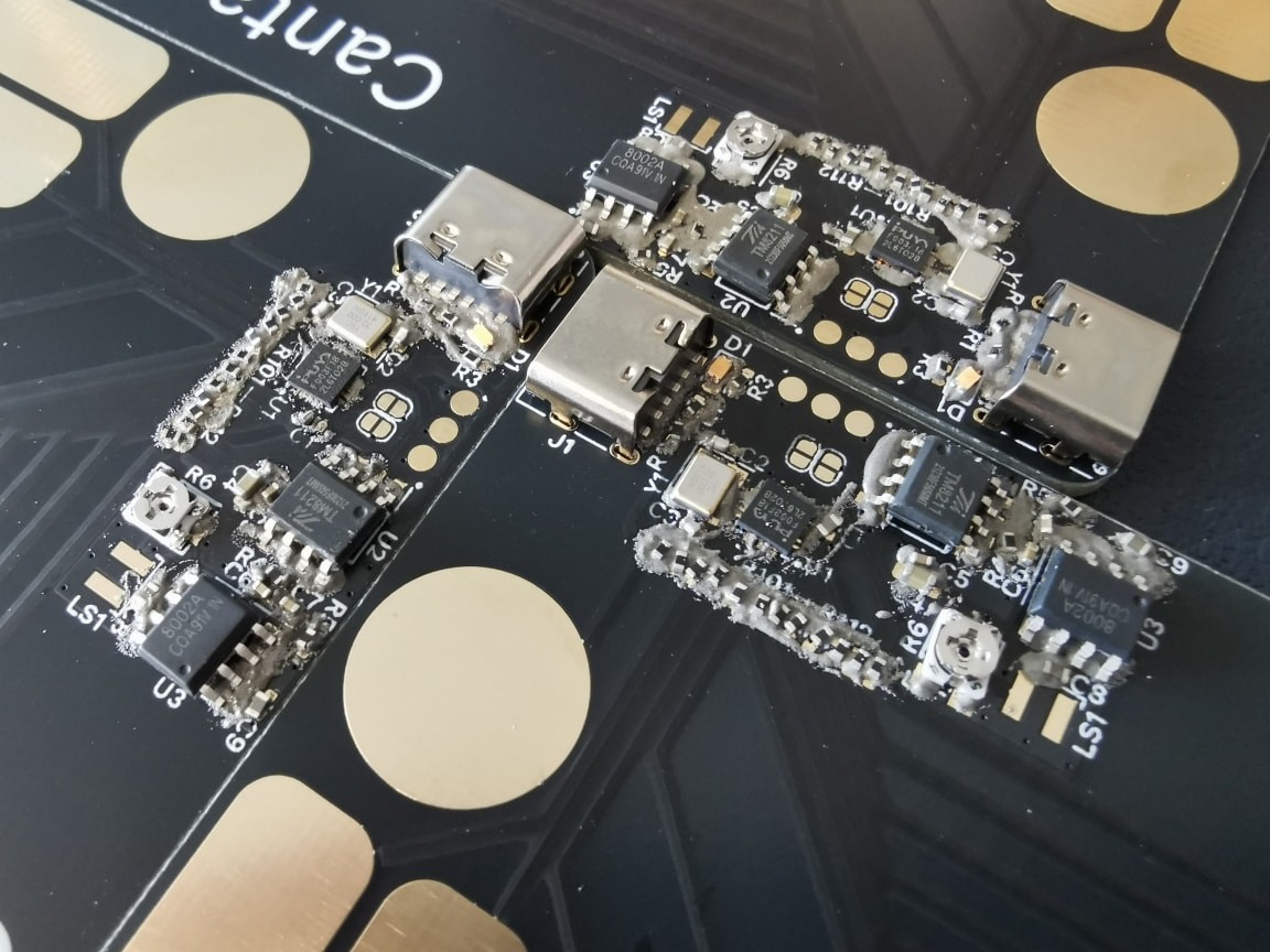


 Anthony
 Kenneth Marut
 Radu Constantin
 greg
greg
Nice! Look forward to the video.