0%
0%
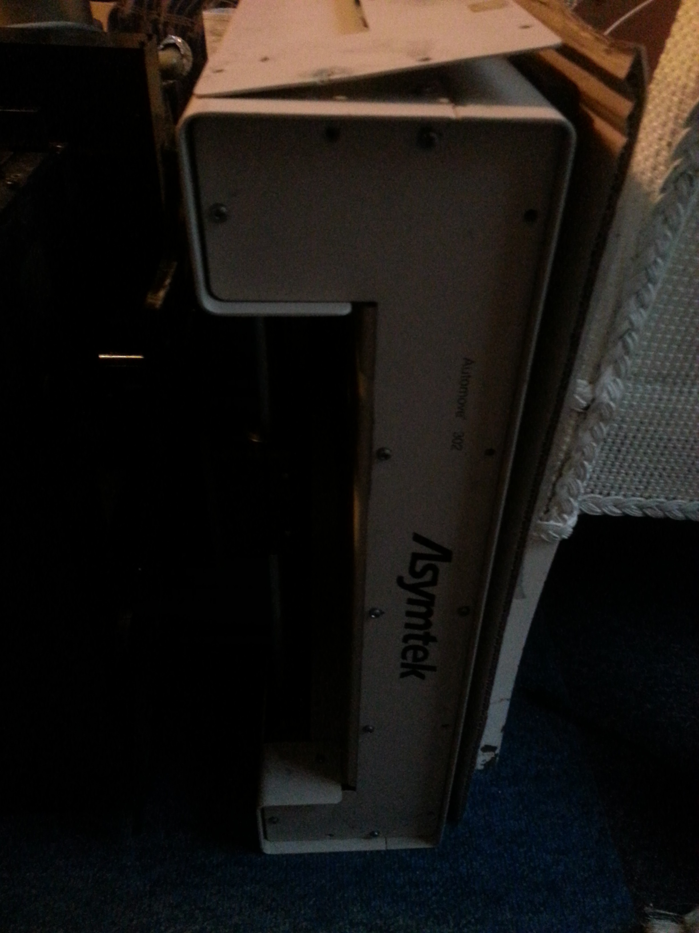
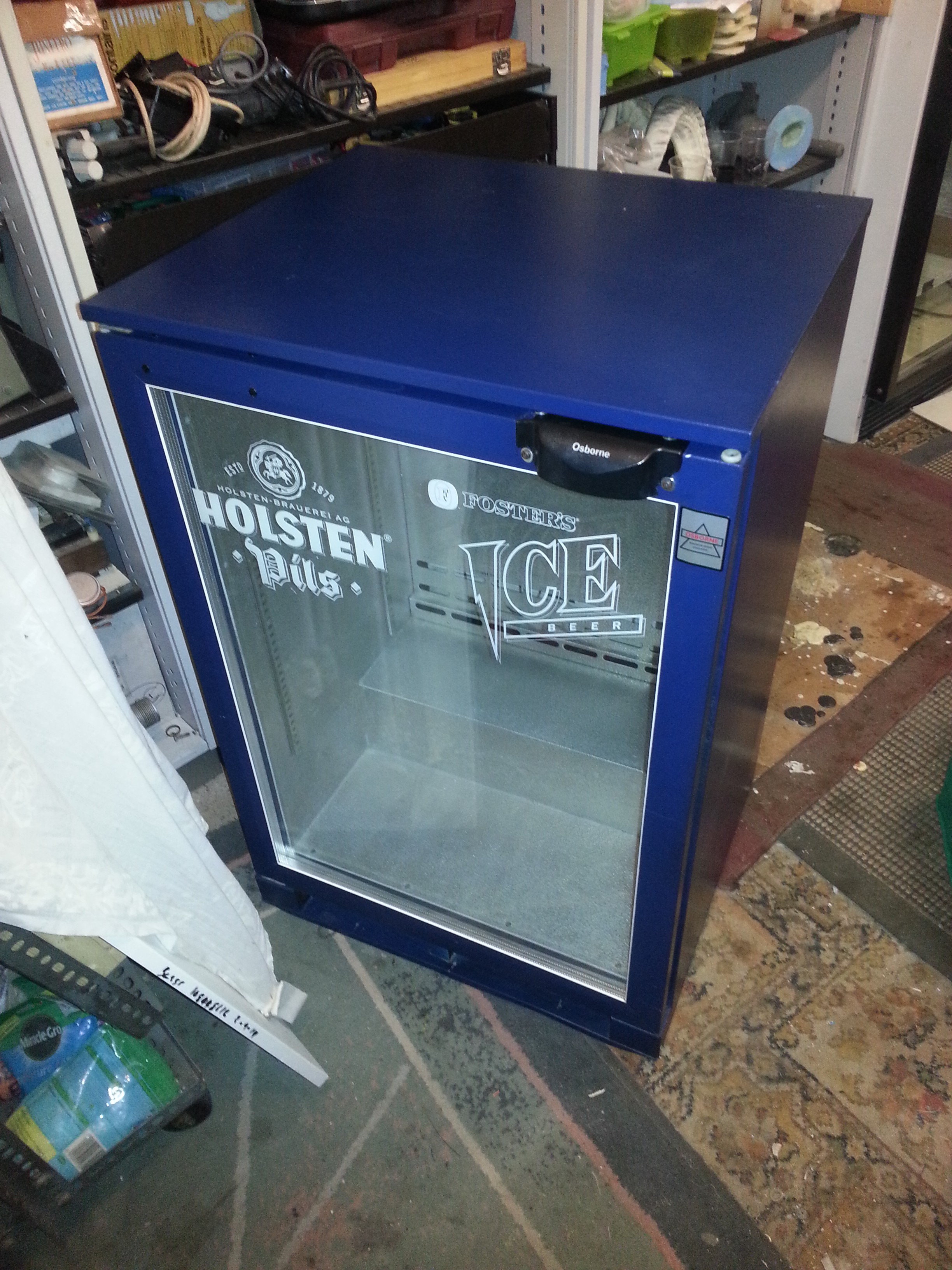
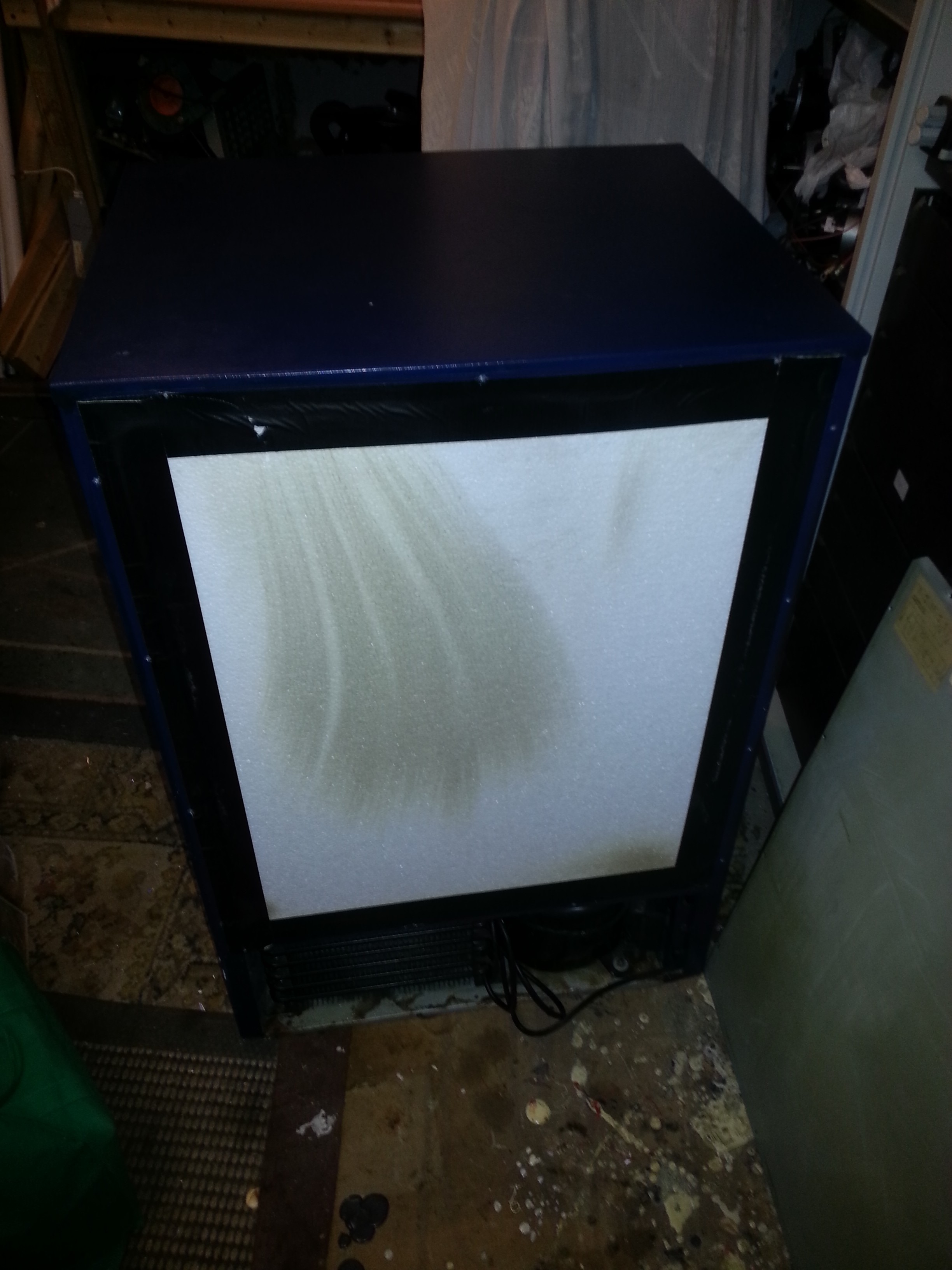
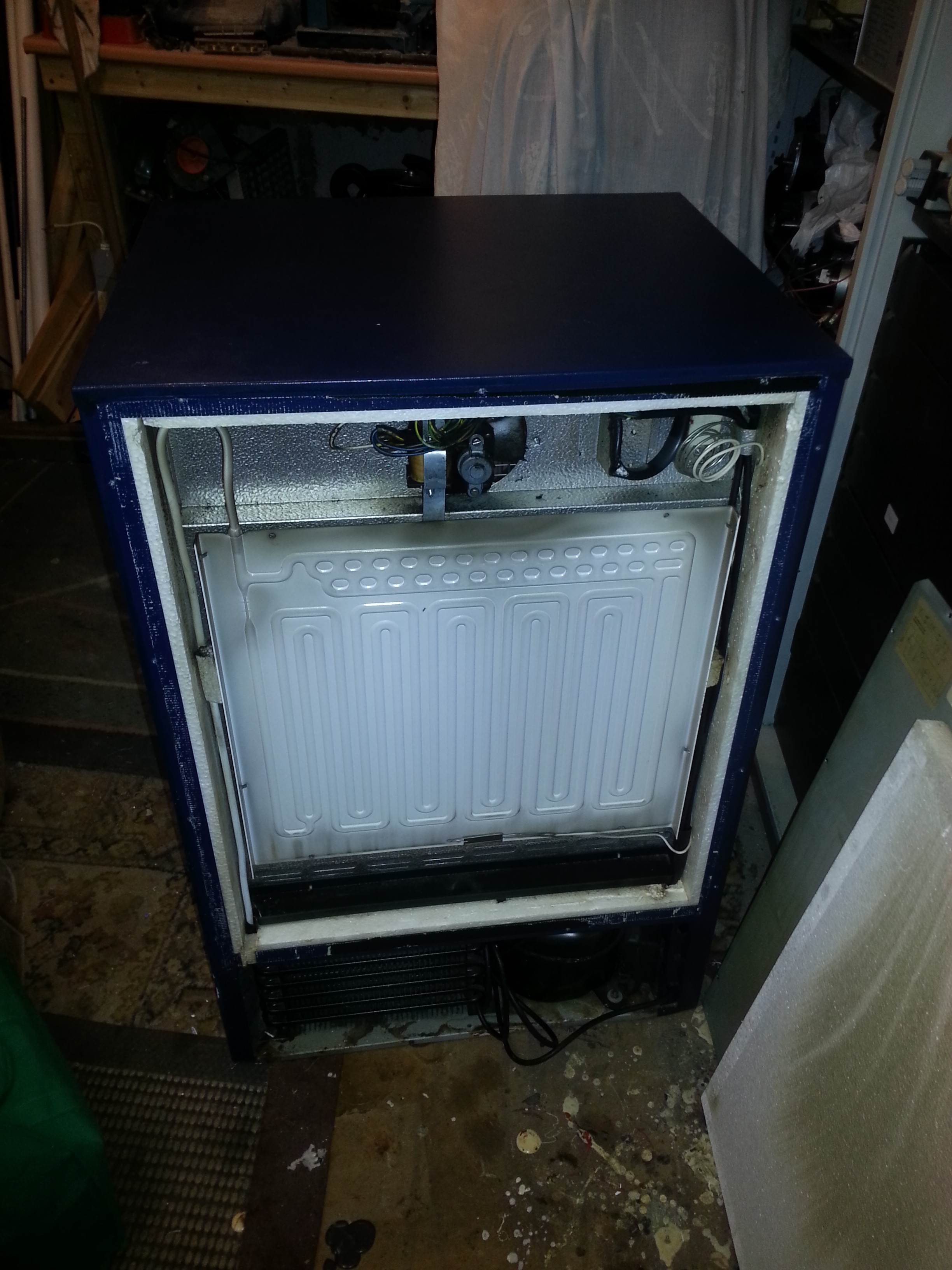
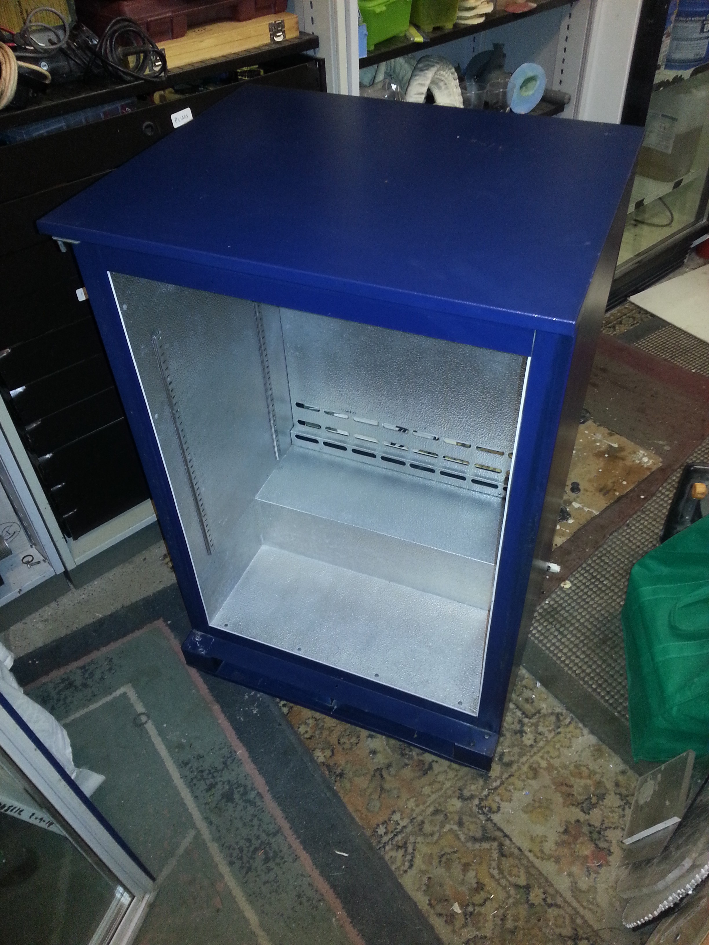
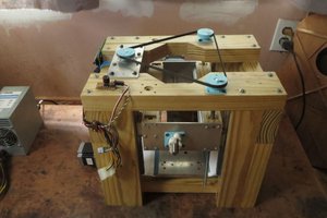
StrataFridge FDM printer
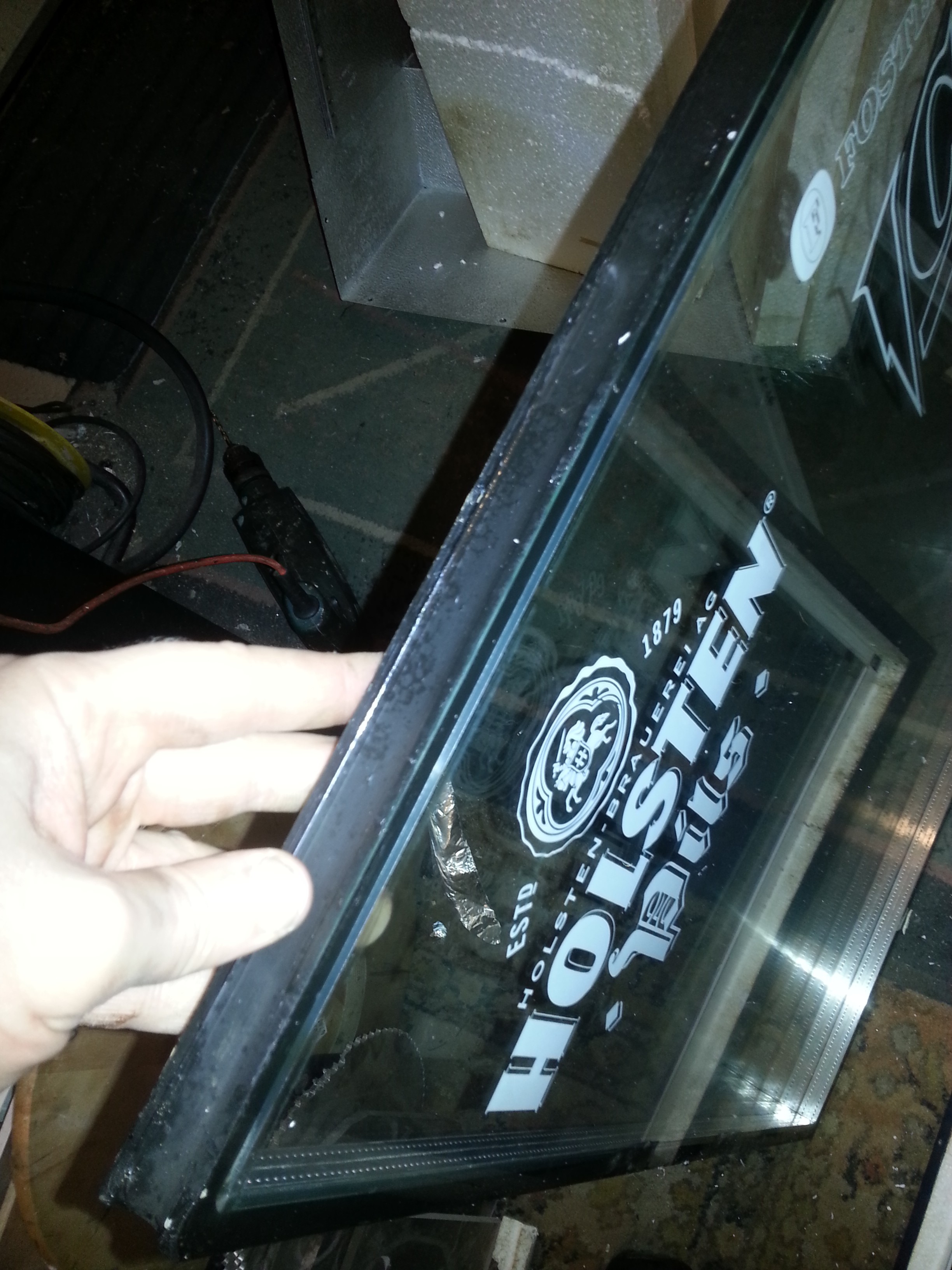
The mechanical guts of a 22yo Stratasys, reengineered & mounted in a stylish drinks fridge.
 Sci
SciBecome a Hackaday.io member
Already have an account? Log in.
Just one more thing
To make the experience fit your profile, pick a username and tell us what interests you.
Pick an awesome username
hackaday.io/
Your profile's URL: hackaday.io/username. Max 25 alphanumeric characters.
Pick a few interests
Projects that share your interests
People that share your interests
 Okay, that actually looks pretty good!
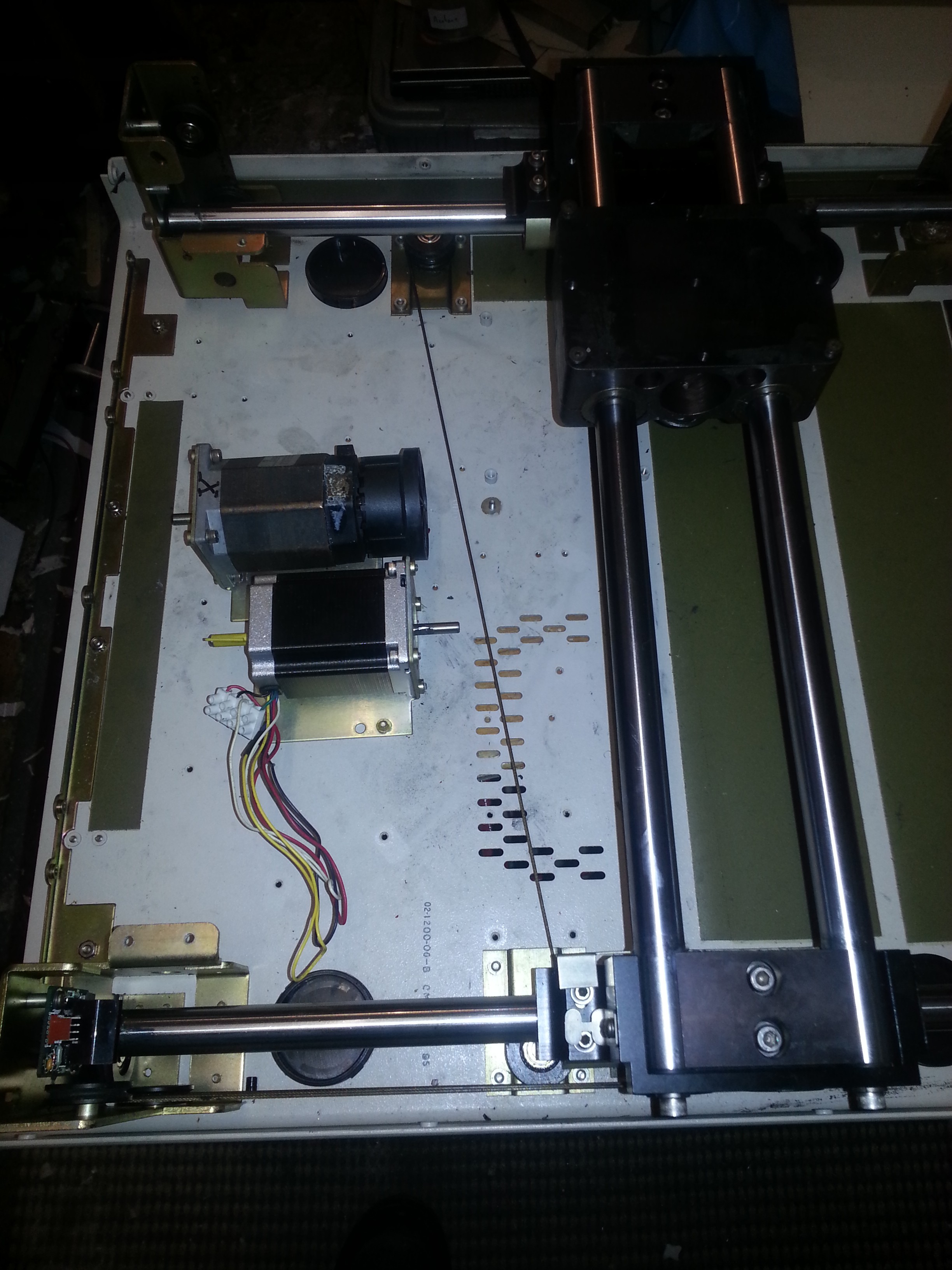


 dekutree64
 Christina Zhang
 Chris
Chris
 ken.do