Close
0%
0%

M.A.B

this project will be used to measure someone's respiratory rhythm via a bracelet installed on your arm.

Similar projects worth following
Why this project: people do not know in what state they are as they cannot measure their pulse and respiratory rhythm at any time.
People who have sleeping problems such as breathing at the same time. Another example, people who have cardiac issues do not have the opportunity to keep track of themselves.


What we want to achieve: create a bracelet that can save all these information and send them to your phone. A History function will be put in place so you can monitor the evolution of your body throughout your experience with our product.

The basic Idea :

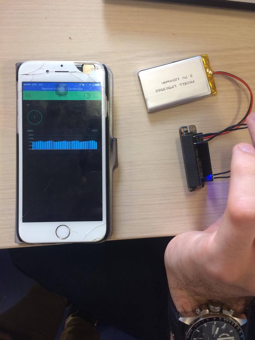
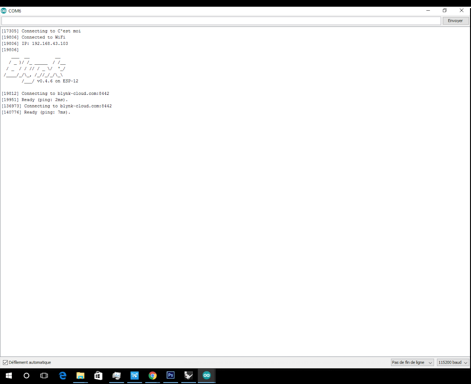
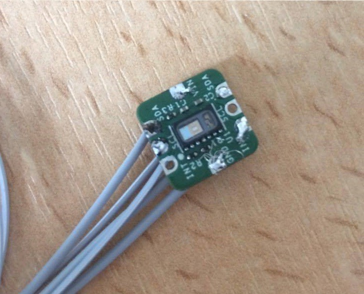
  1. We are going to use the Arduino platform to relay the data recorded by the captor to your phone with the aid of the inbuilt wifi shield.
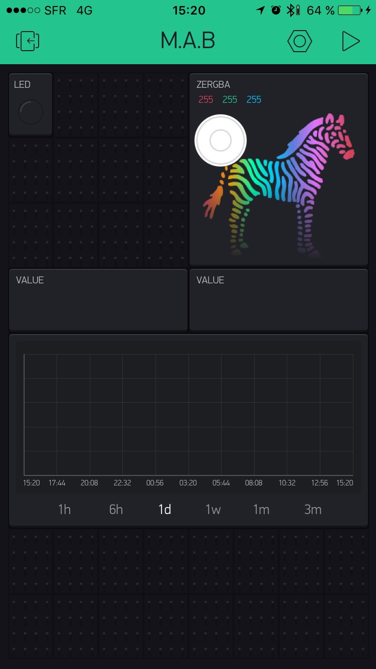
  2. The data will be inalized by the arduino card and then sent to a App on your phone that will display the treated information.
  3. The phone App should be able to display and save the recorded information.

The project should support iOS ( Android is not intended for now but might be added)

    • 1 × arduino 101 we will use this arduino for the prototype
    • 1 × arduino nano used as the proper arduino
    • 1 × sensor SPO2 emits green light and senses when the blood absorbs the green light
    • 1 × battery used for watches especially lithium-ion battery
    • 1 × ESP8266 Huzzah Feather

    • Log 11 : 05/29/2017

      M.A.B05/30/2017 at 07:07 0 comments

      Today we found a new code which collect data on your heart rate and oxygen saturation at the same time. Meanwhile we didn't succed to make it work.

      We cut our wires shorter for esthetic, then we soldered them again to the captor.

      We tested the new code. Nevertheless the code is not working as we wanted. So we came back to our first program.

      Tomorrow we will test a last time our device.

    • Log 10 : 05/21/2017

      M.A.B05/30/2017 at 06:51 0 comments

      Today we have found a way to send captors data to the Blynk app. Then we will be able to take information from the captor with a phone app (see instructions for more détails).

      Now we can push the button in the Blynk app, then you have a graph on Blynk.

    • Log 9 : 05/19/2017

      M.A.B05/29/2017 at 19:35 0 comments

      Test :

      We tried the code and put the data on excel in order to see our hearth rate with graphics.

      Here are the results of 2 tests on sportive man hearth rate before and after an effort.

      We have InfraRed value in y-axis and the number of value sampled in x-axis.

      Observation : we can see the variation of blood volume stable before the effort, whereas after the effort, variations are quite instable.

    • Log 8 : 05/12/2017

      M.A.B05/29/2017 at 08:16 0 comments

      For the captor's code part we found successfully a code on github which will permit us to transform a photosensitive data to an analog data (wavenumbers, beats per minutes). In fact this code read "heart rate" data.

      research source : https://github.com/sparkfun/SparkFun_MAX3010x_Sensor_Library/blob/master/examples/Example5_HeartRate/Example5_HeartRate.ino

    • Log 7 : Connection esp8266 to phone_Blynk

      M.A.B05/05/2017 at 14:46 0 comments

      connected esp8266 to Blynk app via the arduino IDE

    • Log 6 : 04/28/2017

      M.A.B05/01/2017 at 13:52 0 comments

      Today we experienced soldering. After practincing it a little, we immediatly soldered our "spO2 sensors" with 5 wires.

      Here is the final concept :

    • Log 5 : 04/28/17

      Guillaume Audenino04/28/2017 at 13:16 0 comments

      -Mainly finished the 3D making part (unless something goes horribly wrong.)

    • Log 4 : 04/07/2017 - fusion 360 and troubles

      M.A.B04/07/2017 at 13:35 0 comments

      getting further on fusion 360 ;)

      We are going to have one main frame with a second part that will slide in from the top (Y axis), this part will be a "L" that would cover the top too .

      For the way to "lock it" , well we are still thinking about it ... (And to attach it to yourself)

      On the other hand , we still didn't receive the captors and extra parts for our device :( Waiting eagerly for those !

      On the other hand we are also on the programming of the Arduino.

    • Log 3 : 04/07/2017

      M.A.B04/07/2017 at 13:30 0 comments

      • fully finished application on iPhone using Blynk
      • going further on the physical concept of the box
      • coding for the wifi shield

    • Log 2 : 03/31/2017

      M.A.B03/31/2017 at 14:23 0 comments

      1. Starting to modelize the device's shape on fusion360

      2. Dropped Xcode for Blynk

      3. Just received the arduino nano and genuino 101

    View all 11 project logs

    • 1
      Step 1

      You can download the blynk app on the apple store or on the google store etc...

      After you decide to create a new project, they will give you a long list of devices you want your app to be connected to and what type of connections you want. we have chosen the Arduino Nano and a WIFI type of connection.

      As for the content of your app, they will offer you a certain amount of content for free. For our app, there were way enough space for what we needed : to blocs to present 2 values (heart beat + breathing)

      the "hardest" thing to do is to properly connect each of your values to the pins of your arduino

      note : the zebra is a personal touch, had some credits left ;)

    • 2
      Step 2

      or the "chasis" we will be using the 3D software Fusion 360 https://www.autodesk.com/products/fusion-360/students-teachers-educators (free for students)(You can use another one, as long you don't do any thing to complicated they are pretty similar).

      1) Once you download, install and launch de App, You should and on a window that should look like this :If not , go on the second Top left icon and chose "New design"

      2)- Onc we are there we can either do a shape and carve it, or the smart way and make a sketch of our project , then we will shape it withthose information we putted down.

      To do so, you need to select the "New Sketch" options. For any of them you need to chose a reference plane (the plane were you will be aking your 2D drawing)

      From here you can skip to a later part to "press pull" and give some well diserved 3D to your 2D work

      2-1)For a design simple as a box made of rectangle we will use the "2 points rectangle" option to make a rectangle. Note thta you can edit either sides parameters freely. Said box will be a 3.8*7.4*3.4cm rectangle with 2 mm wide walls.

      So we should have a rectangular base by now , but now you want to have walls ! To do so, re-use the rectangle option and make "wall" patern on the base

      (Make thin rectangles on as long as the sides they are suposed to be)(You can use the "Lines" option to make more effisiant and good looking sides)

      By this point your project should look more or less like this.

      3)Great now we can go on to do 3D stuff !To make this plan go to 3D , use the "Create: Extrude" it will basicaly add depth on the part you want to.

      So once you've raised the walls and have a base with a depth of 2mm .

      3-1) After this you need to delete 2mm from the top of one of your walls to create the entering side of the top of the box.

      Once done we need to add a slide opening in the 2 other walls, to do so , draw a shape (preferably a isoceles triangles)

      Once done , extrude those to the other sid of the walls.

    • 3
      Step 3

      FIRST TEST ESP - BLYNK

      1) see first instruction to install Blynk

      2) install ESP8266 huzzah feather board onto the arduino IDE using the following link :

      http://arduino.esp8266.com/stable/package_esp8266com_index.json

      3) Go to File > Examples > Blynk > Boards_WIFI > ESP8266_Standalones

      4) then the program will charge all you have to change is the SSID, PASS and the auth token with is the ID of your BLynk Project

      5) on your blynk app you will want to set it up as a connected to an ESP8266 via WIFI

      6) put a button and set the output onto GP2 which is connected to the ESP's LED and put "switch"

      After everything is done you can put "play" on your Blynk app after you have connected both your ESP and your phone to the same WIFI. When you press on the button the LED of your ESP should turn on the press it again and the ESP's LED turns off.

    View all 7 instructions

    Enjoy this project?

    Share

    Discussions

    Richard wrote 03/18/2017 at 14:30 point

    We all sort of know how we breathe when we are awake but I want to know what goes on when I sleep.  I am told I have sleep apnea, so I would be VERY interested in being able to monitor and log breathing as well as blood/oxygen. 

      Are you sure? yes | no

    M.A.B wrote 03/18/2017 at 22:52 point

    very nice observation richard thanks guess we will have a mode for the day and a mode at night for people who want to know what happens etc... thanks again! :)

      Are you sure? yes | no

    Similar Projects

    Does this project spark your interest?

    Become a member to follow this project and never miss any updates