A smart home offers the possibility of making your life easier and save energy.
For this purpose you have to gather data of your home (the more, the better ;)).
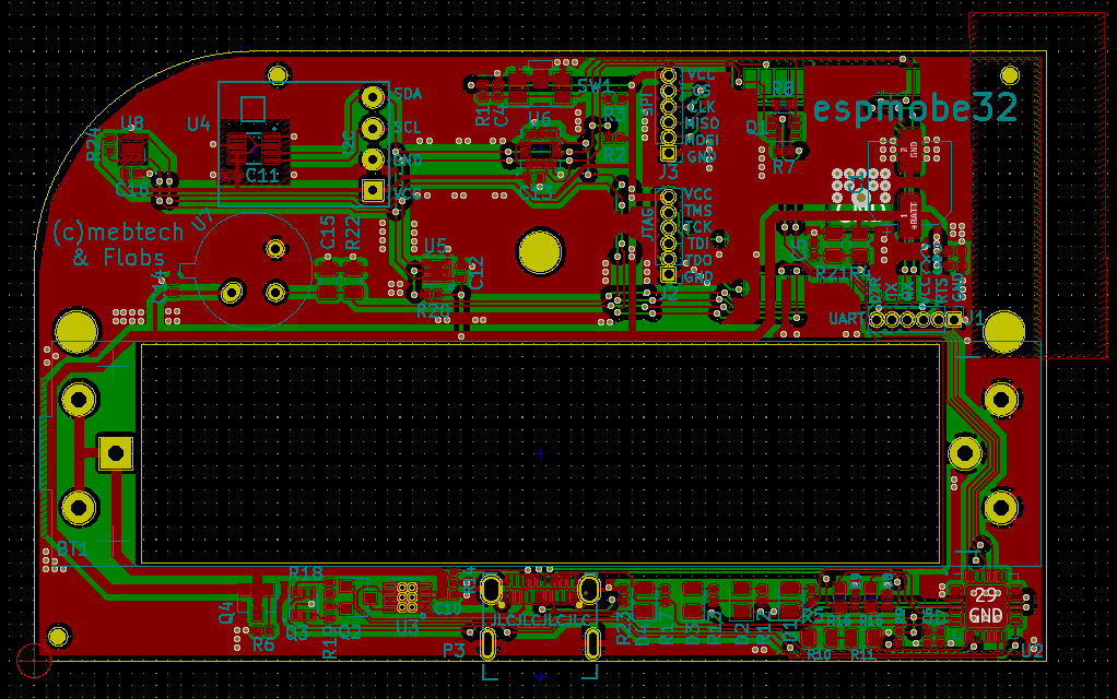
Unfortunately, there are no combined sensors, which fulfil all of my requirements - so I have design it myself - and share it with the community. of course!
Let’s summarize my objectives for this project.
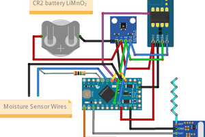
- Battery powered (battery life better than 6 months)
- Wifi and MQTT support
- PIR sensor
- Ambient light sensor
- Temperature and humidity
- Not that expensive
- Small form factor
See also our blog at https://blog.m3k.cc


 mihai.cuciuc
 Open Green Energy
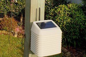
 Christoph
Do you have the code available? I am pulling my hair out trying to figure out how to convert floats and integers to something that mosquitto MQTT can digest. I am trying to get the ESP to report ESP.getVcc();, the battery voltage to MQTT but it does not like integers. I managed to get the "dtostrf" conversion function to make MQTT happy but converting a timestamp (from NTP network time) is proving very difficult to do. I don't know how to make MQTT happy with date stamps.