Patrick Van Oosterwijck
-
Crowd Supply campaign is LIVE!
08/03/2018 at 18:57 • 0 commentsFinally, after 16 months of working on this project, the Crowd Supply campaign is now live, making the LiFePO4wered/Pi+ available to the general public!
If you have been waiting, now's your chance to grab one (or a 10 pack ;)):
https://www.crowdsupply.com/silicognition/lifepo4wered-pi-plus
Check it out!
-
We're releasing on Crowd Supply!
06/22/2018 at 21:21 • 0 commentsWow, it's been a while since the last update, and in case you're thinking that nothing has been happening, you're very much mistaken!
The test/programming fixture is working, production units have been characterized, documentation has been written, and we have been accepted for a big crowd funding release on Crowd Supply!
We're very busy right now going through the Crowd Supply process, which is more involved than I expected. That's one of the reasons for the delay in releasing the LiFePO4wered/Pi+ unfortunately. But, the process is thorough, makes you think through everything, and is designed to maximize your chances of having a great release while at the same time being able to deliver to backers. So it's all good. We recorded raw material for the product video and will be working on editing it into hopefully a rough draft this afternoon. We also built some cool demo's to show off what can be done with it:
![]()
![]()
Some of these may at some point become their own projects on Hackaday.io to help people get started with the LiFePO4wered/Pi+ as well. When I find the time. :)
Crowd Supply is confident that we will be able to go live with the campaign in the next couple of weeks. In the mean time, be sure to subscribe to the project on Crowd Supply so you're kept up to date and will be among the first to know when we go live!
In the mean time, take a look at the Preliminary Product Brief as well. It's very detailed and hopefully helpful in explaining all the awesome features that are available. I realize it's dense and in the future I'll have to make some simple how-to videos or guides to explain how to use certain features, but for now I think it's important to have a document that captures all the pertinent data you may need to integrate this into your project. Let me know if there's anything missing that you might need!
And thanks for all the support and feedback everyone, it's been a long road but we're nearing the finish line. :)
-
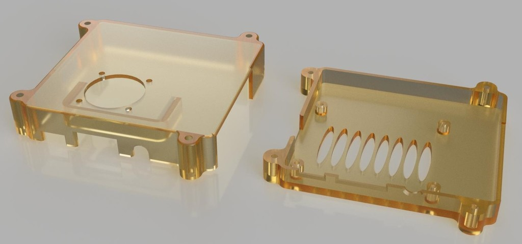
3D printable case design!
03/30/2018 at 21:26 • 0 commentsA customer had created this great looking 3D printable case for the Raspberry Pi + LiFePO4wered/Pi3 and shared it with me. I was very impressed and asked if he wanted to create a case for the LiFePO4wered/Pi+ as well, and he did! The case design is available on Thingiverse:
![]()
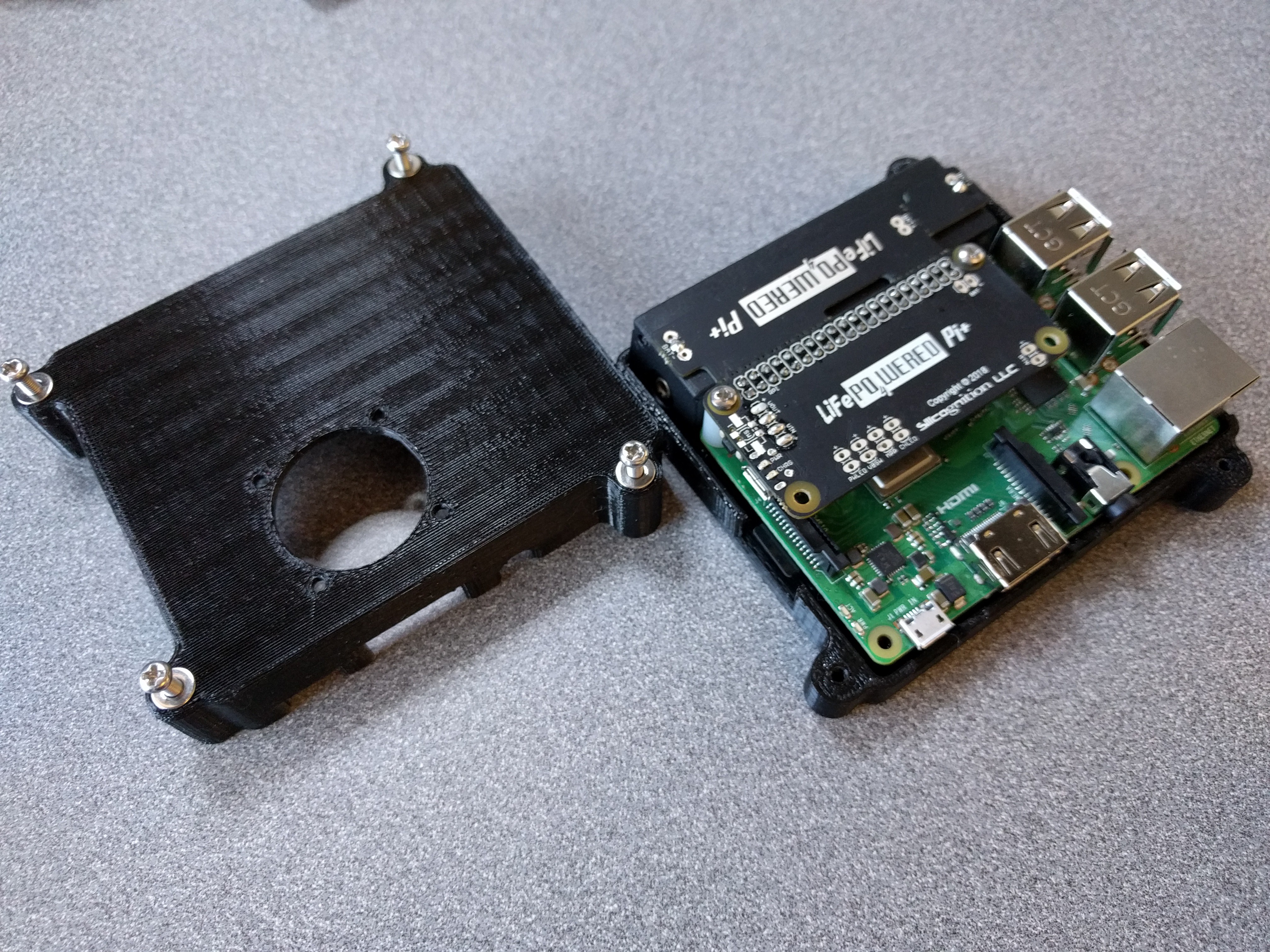
He was also nice enough to send me a sample:
![]() As you can see, the case comes with a hole for a fan, which he had included for me as well. As the LiFePO4wered/Pi+ has pads for the switched 5V output, I used those as power source for the fan:
As you can see, the case comes with a hole for a fan, which he had included for me as well. As the LiFePO4wered/Pi+ has pads for the switched 5V output, I used those as power source for the fan:![]() The result is a nice, solid feeling and compact "computing brick" for having a Pi-on-the-go:
The result is a nice, solid feeling and compact "computing brick" for having a Pi-on-the-go:![]() Because of the active cooling, the system stays nice and cool even under high load. With a Raspberry Pi 3 B+ running with 4 cores at 100% (load average 4.0), the core temperature of the CPU stayed around 62°C!
Because of the active cooling, the system stays nice and cool even under high load. With a Raspberry Pi 3 B+ running with 4 cores at 100% (load average 4.0), the core temperature of the CPU stayed around 62°C! -
Testing 14500 version with Pi 3 B+
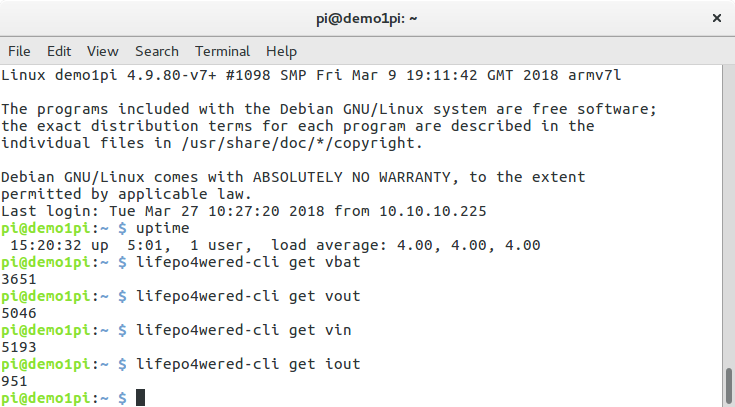
03/27/2018 at 22:47 • 1 commentI was curious if the 14500 (AA, small battery) option of the LiFePO4wered/Pi+ would be usable as a UPS for the new Raspberry Pi 3 B+, so I did a quick test. I ran my Raspberry Pi 3 B+ powered from a LiFePO4wered/Pi+ 14500 prototype, plugged in, for 5 hours with 100% load on all 4 cores (load average 4). After that time, I checked the voltage and current readings:
![]()
These readings are in millivolts and milliamps, and as you can see the battery is full, the output voltage is not sagging, and the Pi is drawing 0.95A.
At that point I disconnected the LiFePO4wered/Pi+ from incoming power. I wasn't sure what would happen: it was possible the battery voltage would sag enough for the system to immediately shut down, or worse, be powered off immediately to protect the battery.
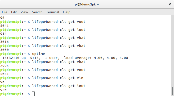
That's not what happened though. The battery voltage immediately dropped a lot (due to its internal resistance) to around 3.1V, but the system continued to run! After about 10 minutes I took these readings:
![]()
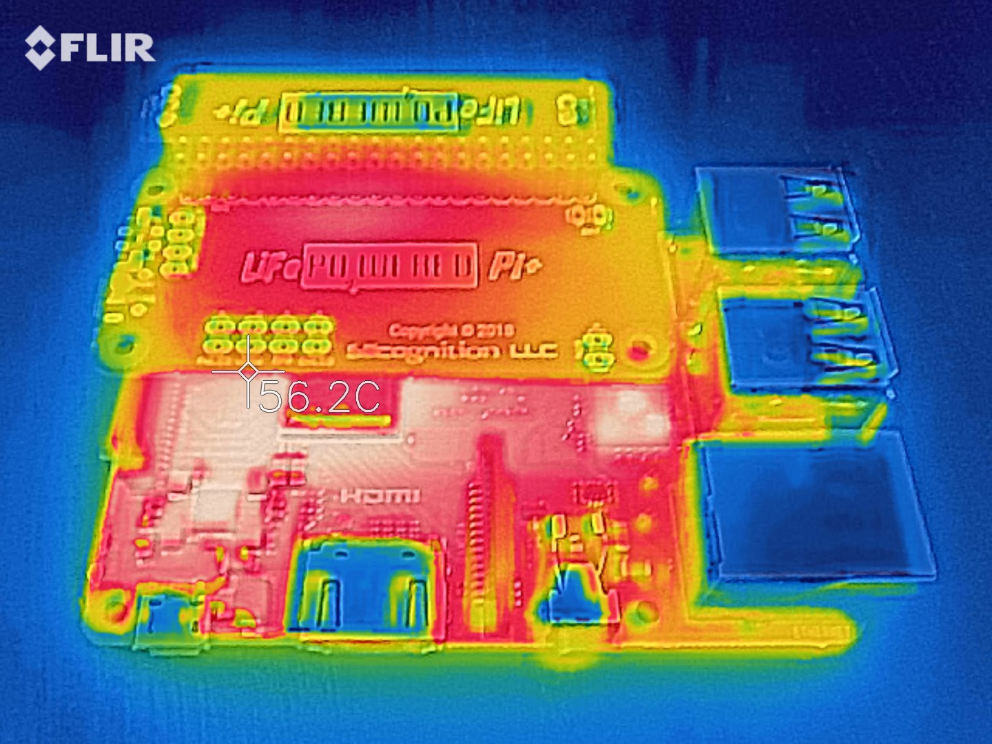
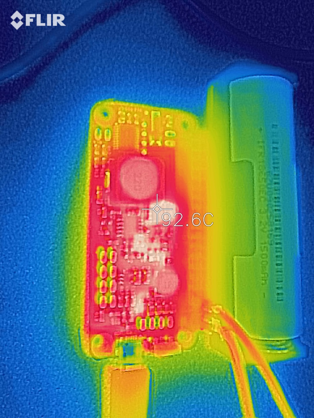
As you can see the load average is still the same, by now the battery voltage has dropped to 2.99V, but the output hardly budged: still a steady 5+V. After about 15 minutes, the battery voltage had dropped enough to trigger a clean shutdown. Just before this happened I took this thermal shot:
![]()
As you can see, the Pi 3 B+ is hotter than the LiFePO4wered/Pi+.
Very happy with this result! It is good news for those who don't care about run time but just want enough power to do a clean shutdown. Even with a heaviliy loaded Pi 3 B+, the 14500 size battery works.
If you're going to do this, I recommend using the AUTO_SHDN_TIME register to either trigger an immediate shutdown or timed to 5 minutes or so, to reduce stresses on the battery. If you want the system to keep running as long as the battery can support it, I'd recommend bumping the VBAT_SHDN to 3000 (3V) or even 3050 (3.05V) though. The reason is that the boost converter experiences a lower input voltage than the one measured by the micro due to the charge current limit resistor which drops more voltage at high current, and you don't want the boost converter's low voltage cutout to trigger and turn the output off before the micro decides to do a shutdown.
-
Progress report
03/25/2018 at 00:13 • 0 commentsTime for another update!
First of all: the question of Raspberry Pi 3 B+ compatibility! I have to admit I was nervous when I heard that the Raspberry Pi Foundation was going to announce a new product on 3/14. What if they announced something new that wouldn't work with the LiFePO4wered/Pi+? That would have been horrible: to make a product that would have been obsolete before it was even released!
Luckily that didn't happen. A quick inspection of pictures made me pretty confident that there were no mechanical issues and after ordering and testing one I can now confirm that the LiFePO4wered/Pi+ is fully compatible with the Raspberry Pi 3 B+! :)
![]()
Aren't they cute together? Also, I'm quite happy with how the naming turned out: the LiFePO4wered/Pi+ works great with the Pi3 B+. :)
I also received my test fixture boards and built three of them last week. There were a couple of issues I ran into. For one thing, I accidentally ordered some OPAMPs in MSOP8 packages that didn't fit on the SO8 footprints, so I'll have to order the correct ones and add those manually. I also had some trouble initially with the on-board USB hub, after a day of debugging I found that I needed to add 15K pulldown resistors to the USB data lines and that made it all work.
Here's the one working board I have (the others are still missing the OPAMPs):
![]()
The big power transistor on the left will be working as a shunt regulator to simulate a battery at various levels of charge. The two other power transistors will be electronic loads connected to the main 5V and switched battery outputs that can be configured to different load current levels while I monitor voltages.
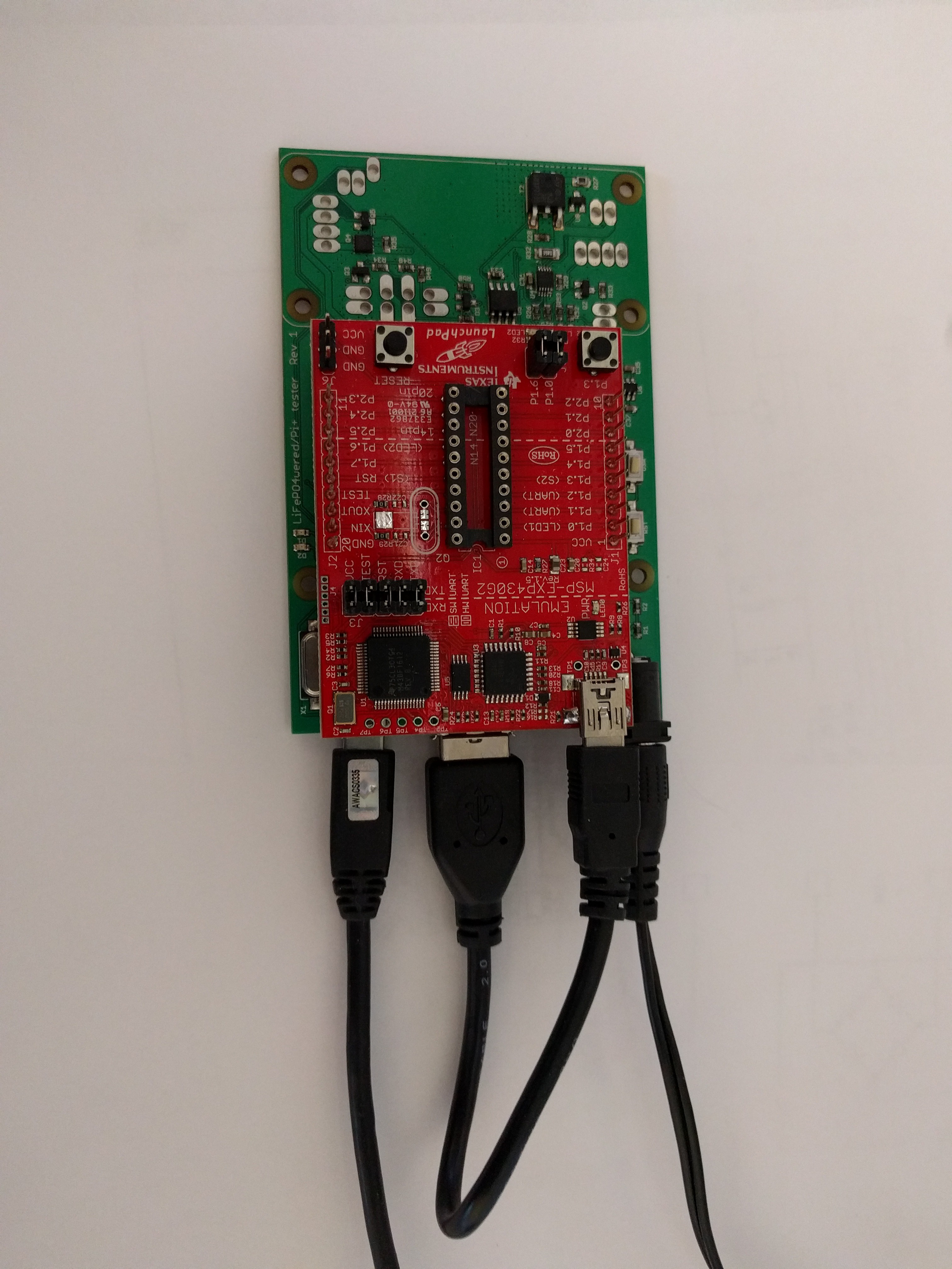
And here's how the Launchpad board fits on top to do the programming of the MSP430G2332 microcontroller:
![]()
By integrating the USB hub, it has become a nice compact system that only has one USB connection to the controlling PC.
I still need to add the pogo pins to the exposed end that will connect to pads on the LiFePO4wered/Pi+ to do the testing. But before I do that I'll be writing some test code first to make sure the circuitry in that area works as expected since access to this area will be much harder once the pogo pins and supporting PCB are in place. Once the USB hub was working, it was quick work to program the Espruino firmware on to the micro, which should speed up the test development nicely.
I also have been doing more testing of production LiFePO4wered/Pi+ boards, including some statistical characterization. The final numbers still require more samples, but it's looking good. The 18650 battery version supports 2A load current with some margin both when plugged in and running only from battery. The 14500 battery version supports 2A when powered by a quality high current power supply, but when running from only the battery it looks like only 0.7A is reliably supported. The reason is the higher internal battery and circuit resistance when using the smaller battery, which makes the battery voltage drop under high load. So if your system is using a Pi 3 or Pi 3+ under high load, the 18650 version is the way to go.
Meanwhile the thermal image under 2A load looks very good with the production boards:
![]()
I have the impression that with the 2oz copper production PCB the heat spreads even better across the PCB than it did with the 2oz prototype boards. The heat also nicely stays away from the microcontroller and 32 kHz crystal, which is exactly what I want to see.
I've been updating the product briefs for the LiFePO4wered/Pi and /Pi3 to include more information on hardware connections. I'll be using the document for the /Pi3 as the basis for the new document for the /Pi+, so it made sense to fill it out with as much up-to-date info as possible before doing that. Hopefully next week I'll find some time to work on that.
Lots going on and getting closer to general availability, stay tuned!
-
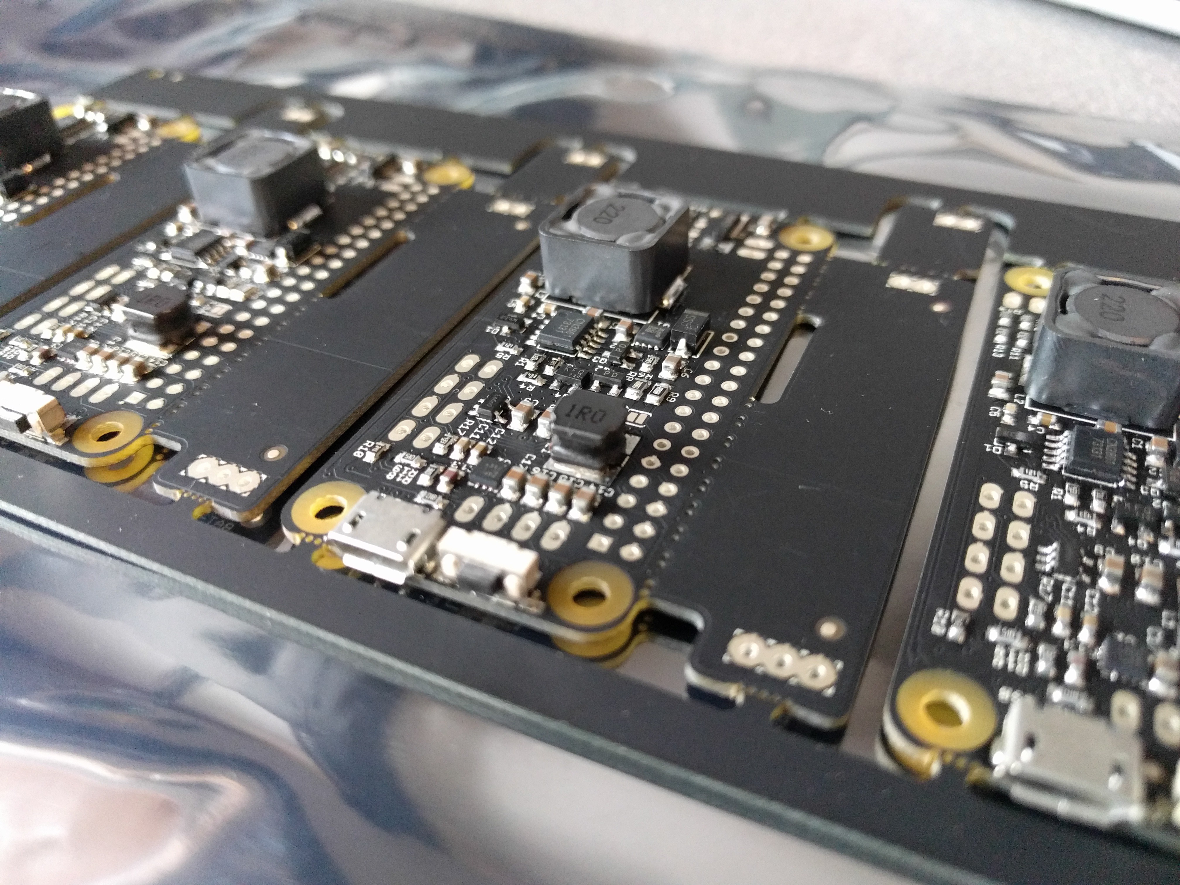
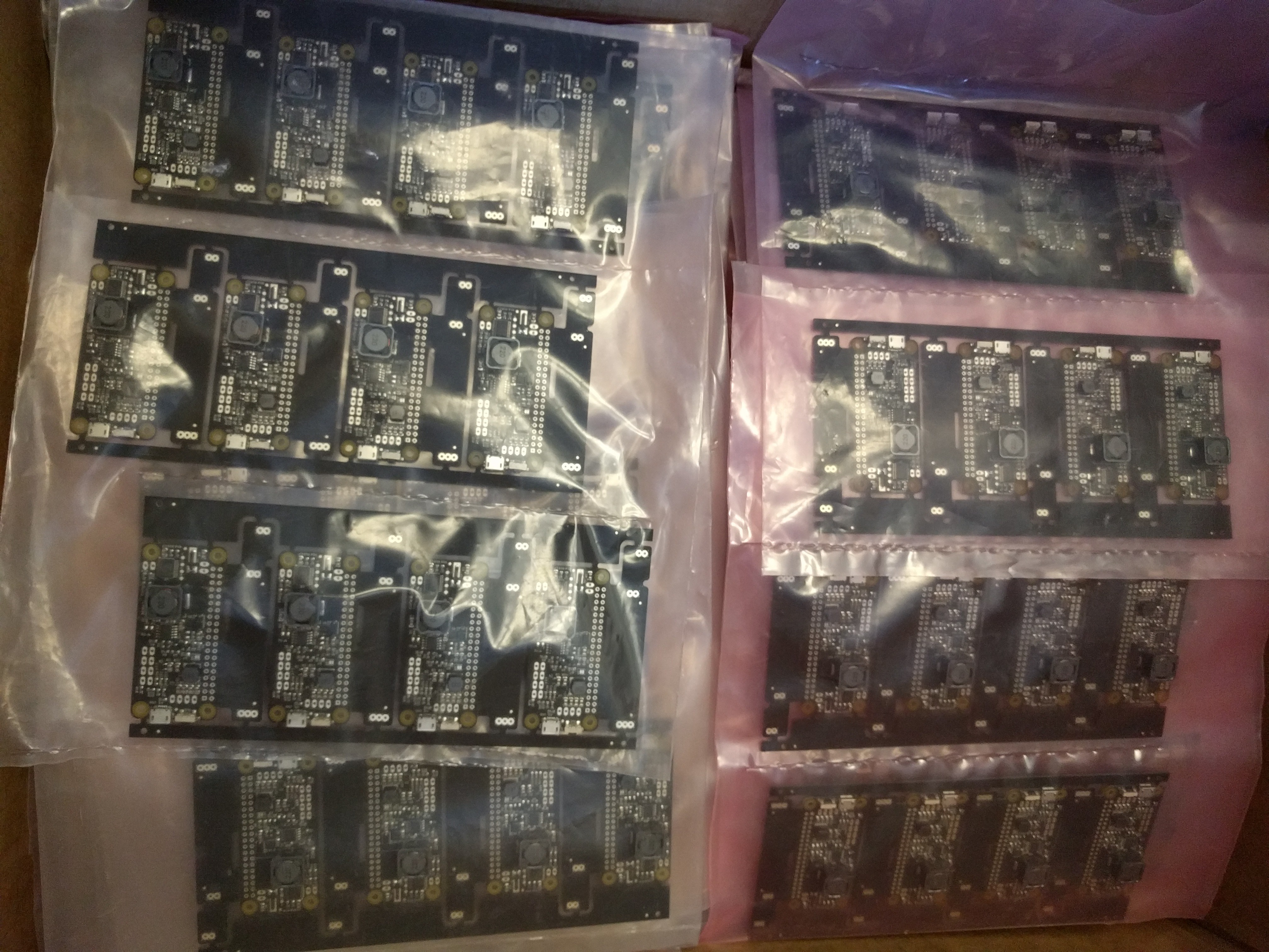
Production boards!
02/17/2018 at 00:06 • 2 commentsIt's been a while since my last update, but a lot has happened!
For a start I ordered production boards. This time I decided to try another company than Elecrow. My local CM had told me the boards could be better, especially the lead free HASL finish wasn't ideal in flatness to work well with tiny DFN packages. I had received "spam" (unsolicited email) from several Chinese companies offering PCB services. After getting quotes from several of them, I chose a Chinese company called XR-PCB because they seemed responsive and easy to work with, panelized my board for free and their quote was reasonable. I went with matte black solder mask and immersion silver finish. When I received the boards I was very happy: they are beautiful!
![]()
The CM was also impressed with them: nice finish, good registration and alignment, nice flat finish.
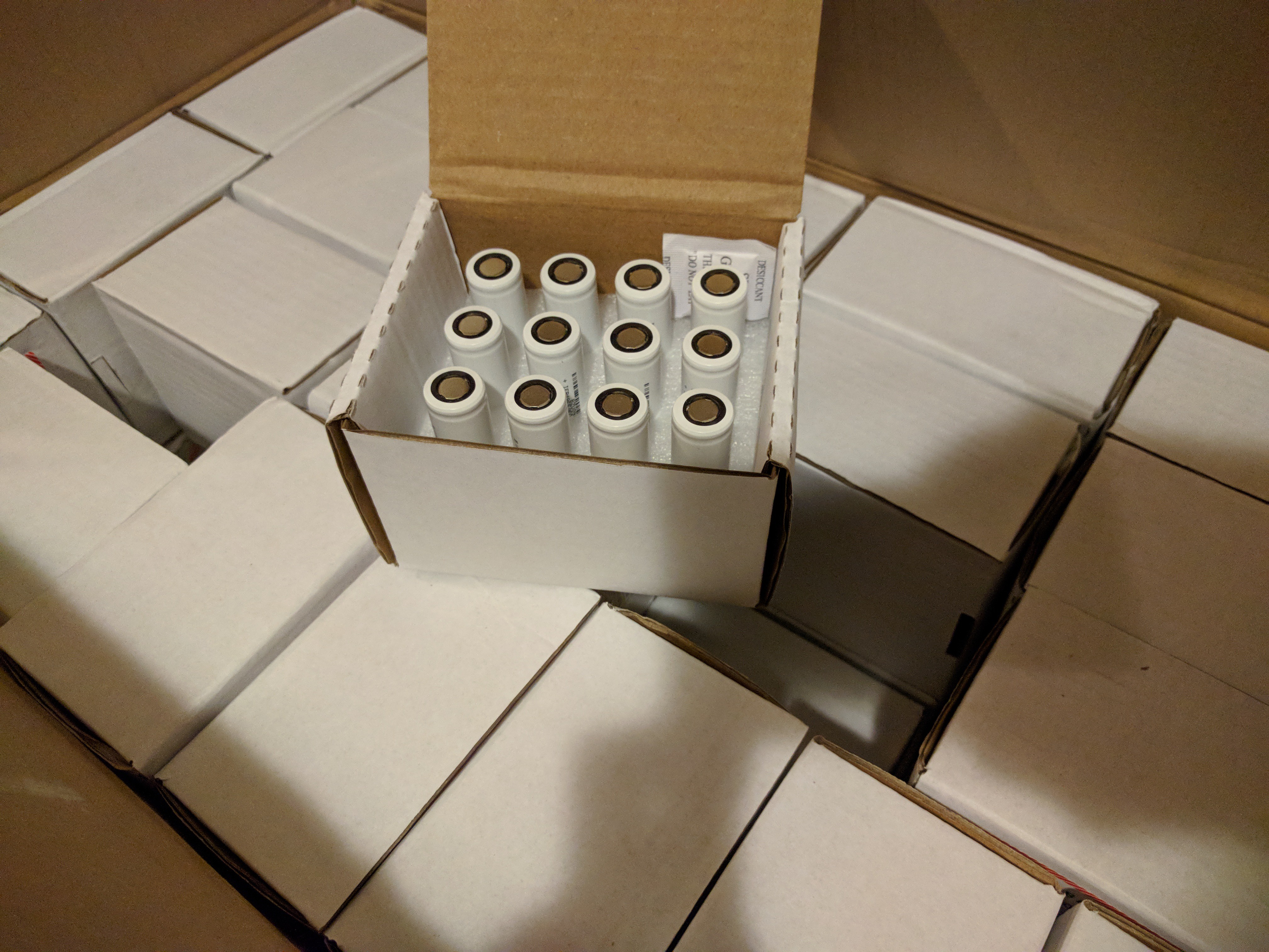
So I collected all my components and they started a build. Meanwhile I also received a new shipment of batteries to be ready for production:
![]()
On Tuesday the CM started production and I received a "first article" panel:
![]()
Definitely an advantage of living in a city where the CM is literally down the street! :) The first article boards tested out fine, no issues. So I gave the green light to finish the rest. Which I received today:
![]()
It's happening people, almost there!
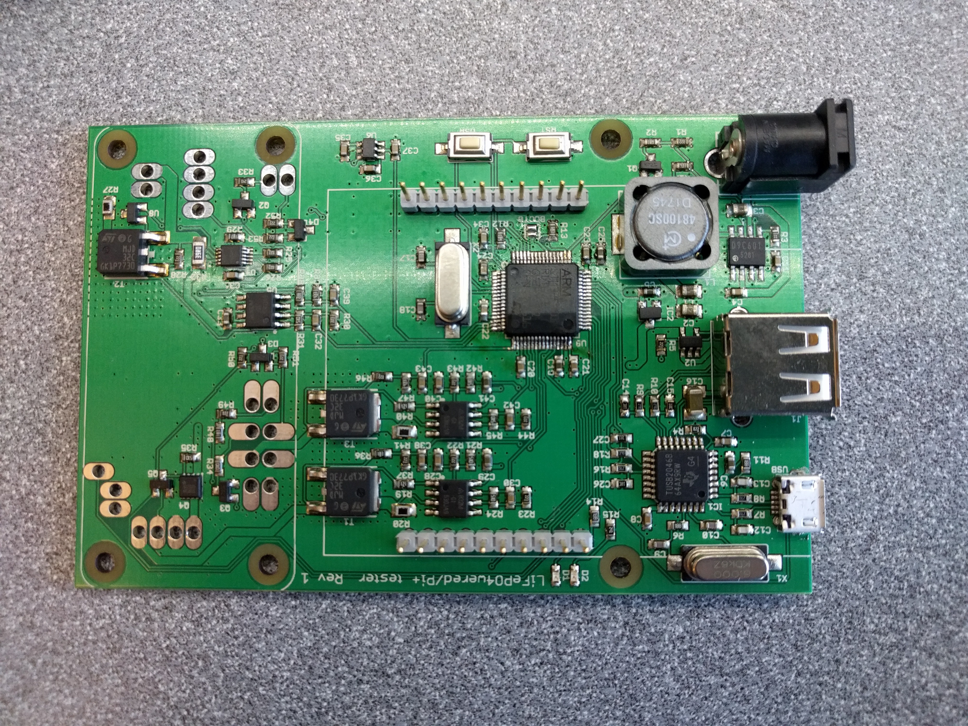
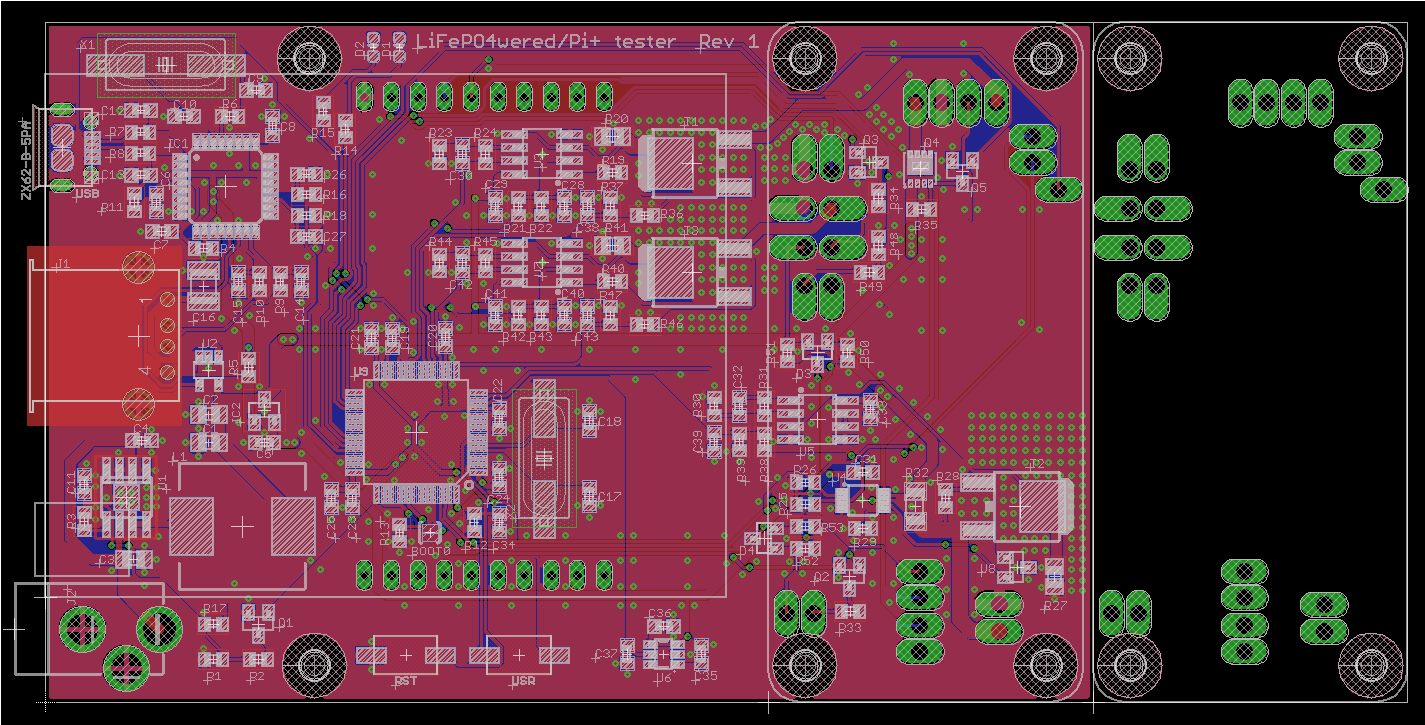
In the meantime, I'm working on the product brief / manual, and need to update the web site. I've also been hard at work creating a test fixture. Using that I will be able to test these more thoroughly and faster than testing them by hand as I do with my current production boards. Funny thing: the test fixture ended up being a more complex design than the product it will be testing:
![]()
I'll be using a TI MSP430G2 Launchpad board as programmer, it will plug in on top of the main board. There are two programmable loads to test the 5V and auxiliary outputs under various load conditions. There is a "battery emulator", which is in fact a shunt regulator. I'll be able to use it to test the behaviour of the DUT under various "battery levels". Controlling it all is an STM32 which is configured the same as the Espruino Pico, so I will be able to use the marvellous Espruino firmware for quick development of the test functions. Initially I had intended to drop an actual Espruino Pico module on the board, but I ended up needing more pins than those broken out to the castellated edges, so I opted to so a bare board design. The remaining functions on the board are a beefy power supply and a USB hub to be able to run the Launchpad board and the Espruino from a single USB cable going to the test PC.
So I'm now in a position to start selling these in limited quantities (manually tested for now, and lacking documentation). I have decided to position them as a "professional" B2B product initially, and I'm holding off on making them generally available through a store front for now. The LiFePO4wered/Pi and /Pi3 will continue to be sold on Tindie for the general public, as long as I have stock. When stock runs out, the roles will reverse: the LiFePO4wered/Pi+ will become the publicly available product and the legacy products will only be available for volume buys. This will hopefully give me enough time to get the test fixture and documentation finished before general availability.
Professional customers who want early access and don't mind paying a little extra for manually tested boards can contact me directly and I will be able to get you early samples! :)
-
Power supplies, final PCB design
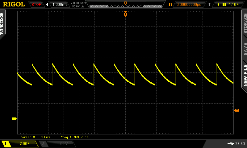
01/16/2018 at 01:01 • 1 commentHad a little bit of a scare this morning. I arrived at my office and noticed that the LiFePO4wered/Pi+ I had intended to be running at 1.8A load over the weekend had turned off. Off as in "the micro had determined the battery voltage was too low and switched to off state". This was especially weird since the charge LED was on, and the input voltage was around 5.5V. My first thought was of course "oh no, what has died?" :)
I measured the voltage across the current sense resistors and it was zero V. With 5.5V on the input and the charge LED on, it seemed "obvious" that something on the LiFePO4wered/Pi+ was faulty. So I moved the setup over to my other workbench where most of my measurement tools live so I could scope what was going on, plugged it in to the power supply that was there and... the voltage across the current sense resistors was 120mV as it should be! Everything was normal.
Ok, move it back to the test bench, plug it in there... and 0V across the current sense resistors! What the heck? Was it the location? Brought the supply from the other bench over... 120mV. Seems something is wrong with the power supply on the test bench, but how can that be, since I measure 5.5V on the input? Let's scope it:
![]()
Ah I see. The power supply did go bad. Whenever the charger on the LiFePO4wered/Pi+ starts to draw power, the voltage collapses. So the charger gives up, and the voltage returns. Over and over, without actually providing any charge current.
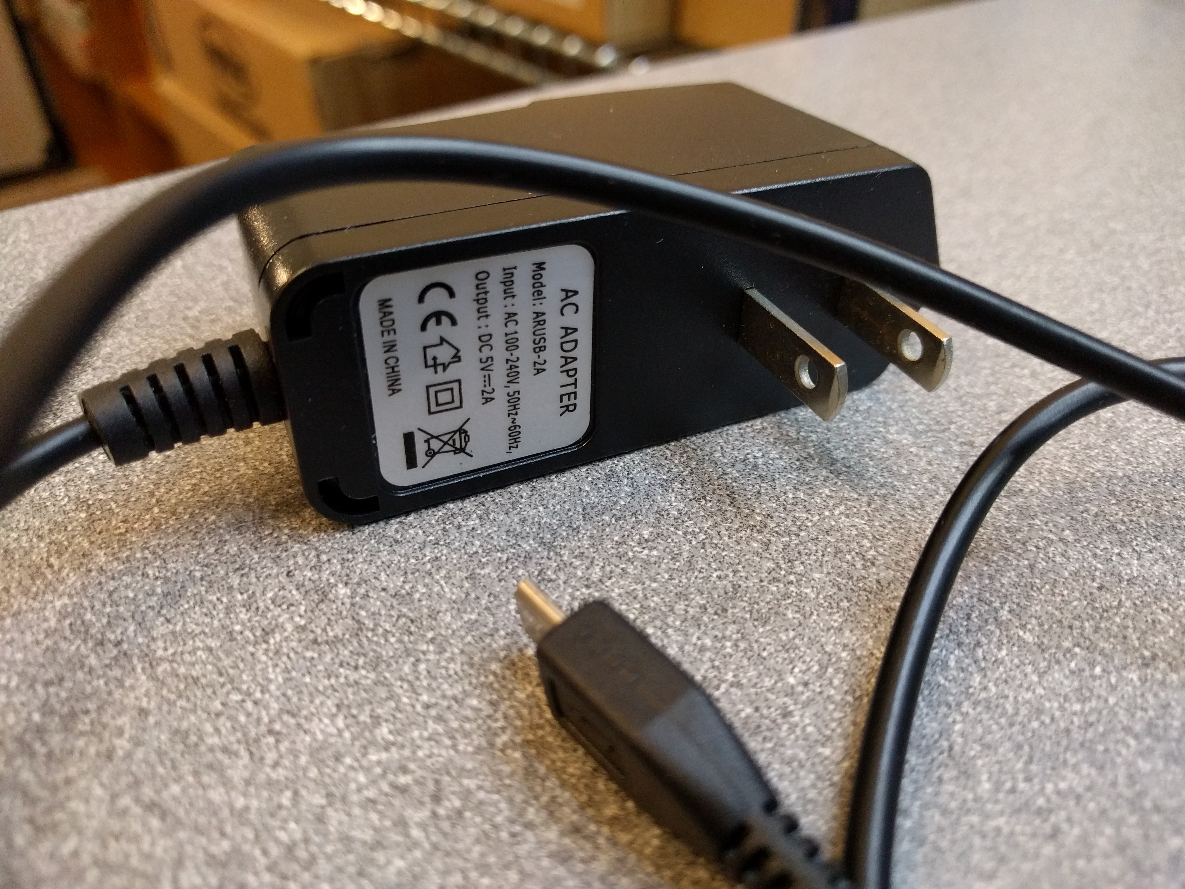
Now this was not my cheapest power supply from eBay or AliExpress. I got this one as part of a Pi Zero kit at Microcenter. It's rated 2A.
![]()
Choosing the right power supply is going to be important for those who will want to push the LiFePO4wered/Pi+ to its limits. Due to the nature of power conversion, the LiFePO4wered/Pi+'s efficiency is not 100% but around 75% instead at 2A load (much better at lower load). The charge converter uses an asynchronous topology and has around 85% efficiency, the boost converter has around 90% efficiency in those conditions. Combine them, and you're around 75%. This means that to support a 2A load, the power supply will have to provide around 2.7A.
My experience is that most 5V wall warts are not able to do that. Even if they are rated at 2.5A, they start to sag seriously around 2A. Since the LiFePO4wered/Pi+ has a smart charger that can be used with weak supplies and solar panels, it will automatically reduce charge current to ensure the input voltage will not sag below 4.65V (the default MPP set point). So I'm sure I'm going to get complaints from people because they are using a lousy supply that sags but they will blame the LiFePO4wered/Pi+ for not working as a UPS at high load. :)
That is a protection feature though to prevent the power supply from being overloaded. Therefore it's odd that the one shown above died on me.
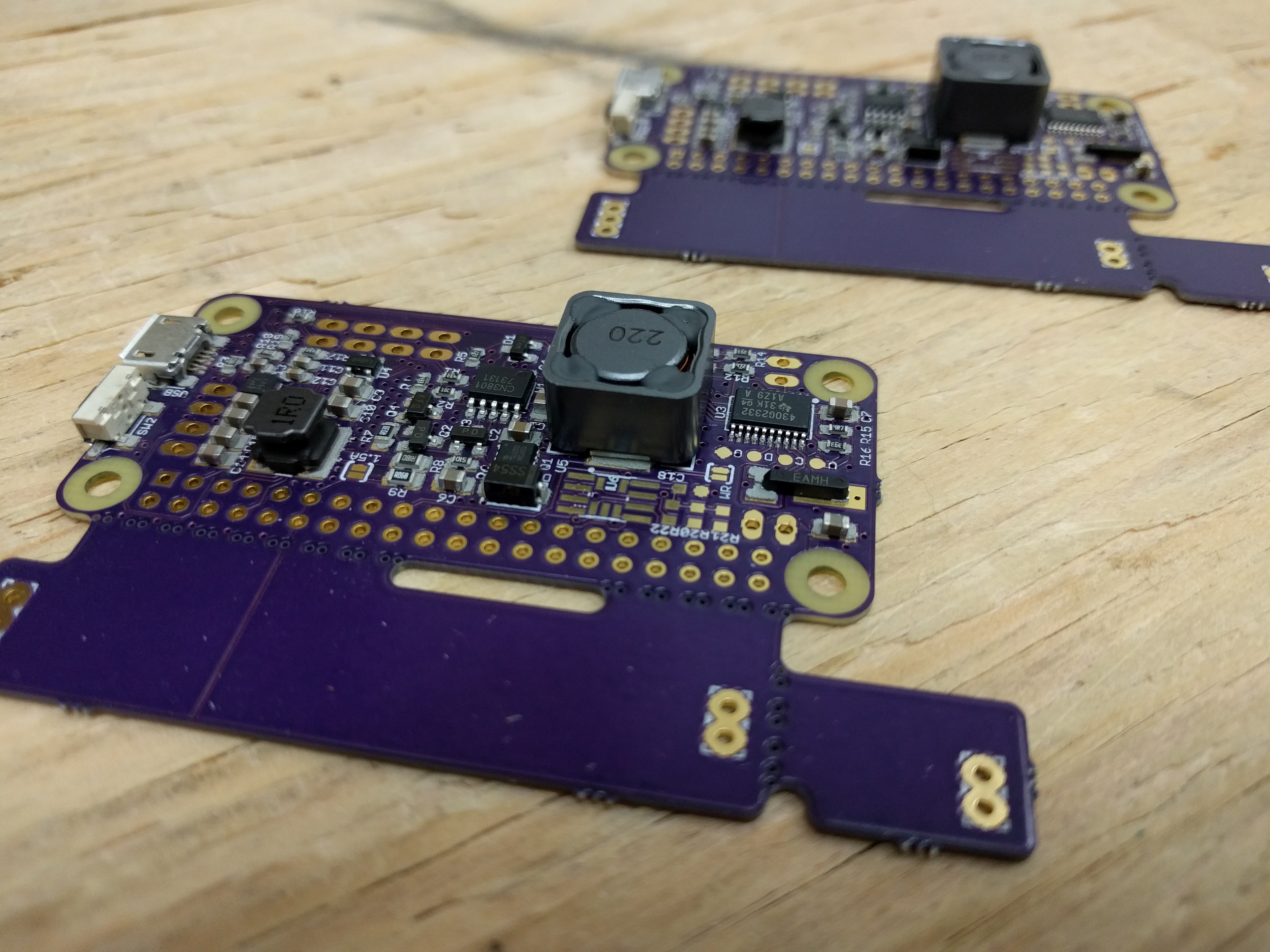
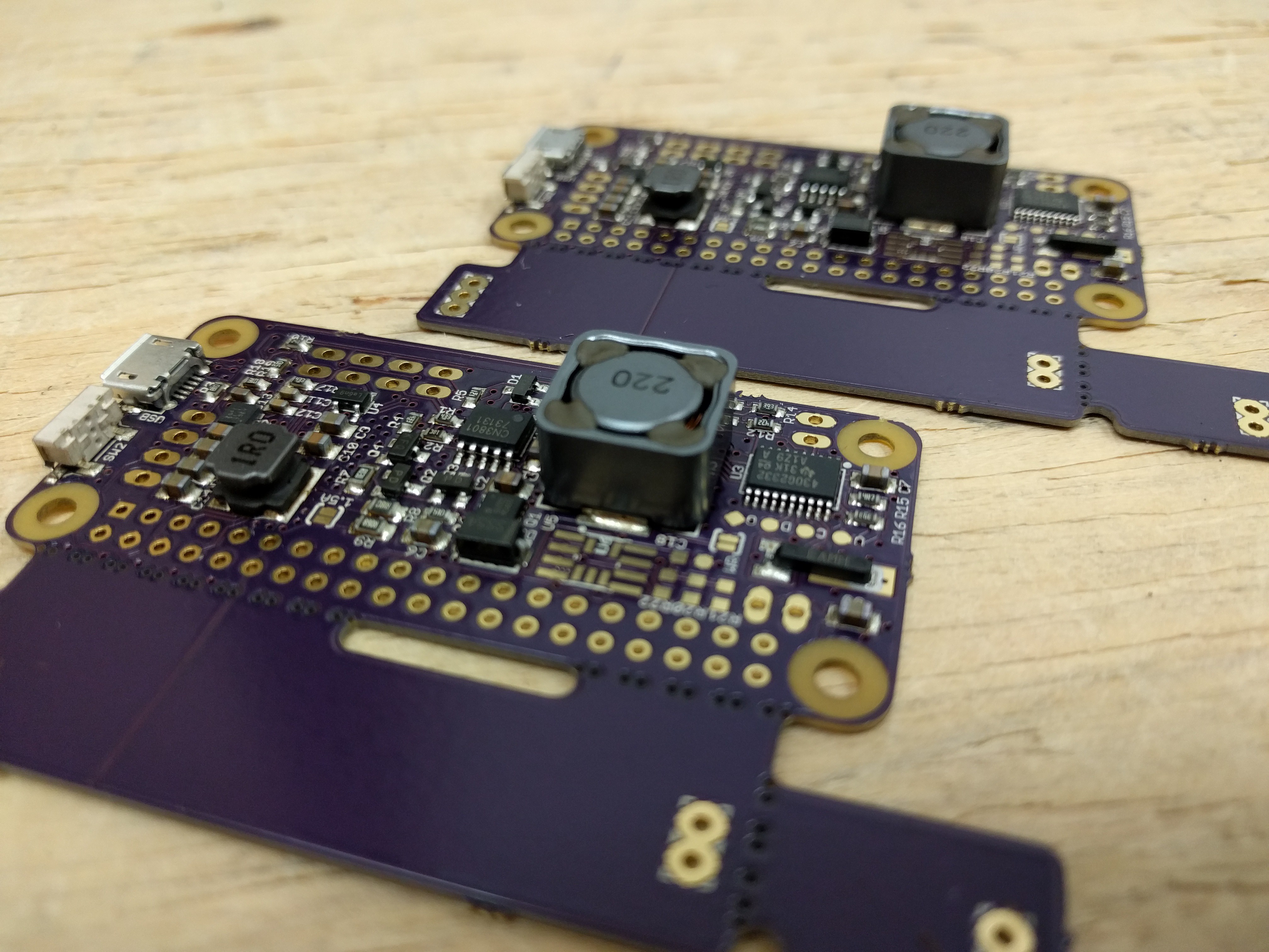
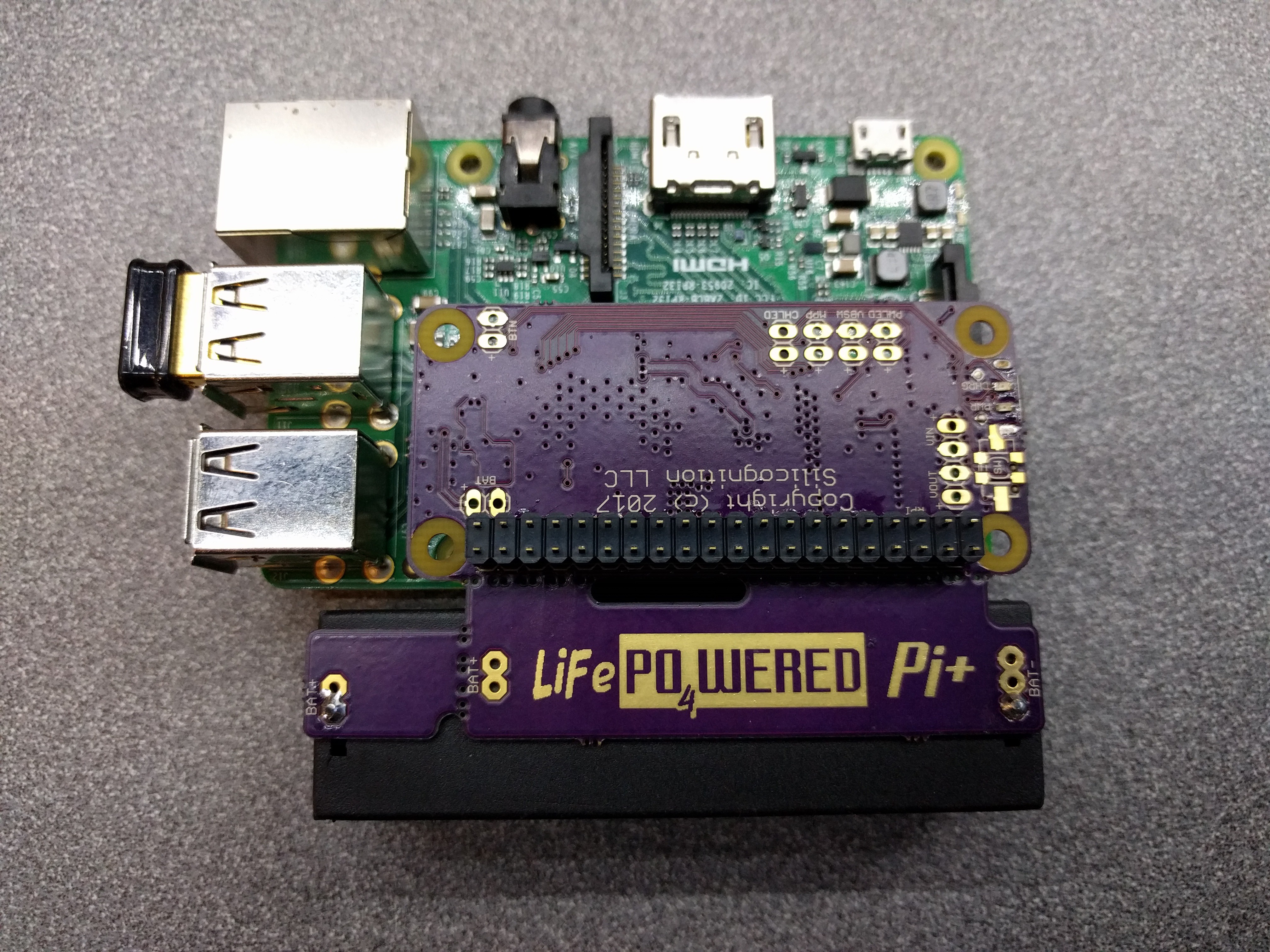
On another note, I am now talking to PCB manufacturers to have production panels made. I've finalized the design and decided to have the PCB manufacturer take care of doing the panellization this time. Here's the final design they are working with:
![]()
![]()
As you can see, I improved the silkscreen with some custom artwork, removed the unused HAT EEPROM and related components and put some more copper there instead for better heat dispersion. The logo on the battery holder part is made by removing solder mask, so in the final product it will be silver in a black background, which will hopefully look cool when it sticks out of a case. :)
-
Thermal images
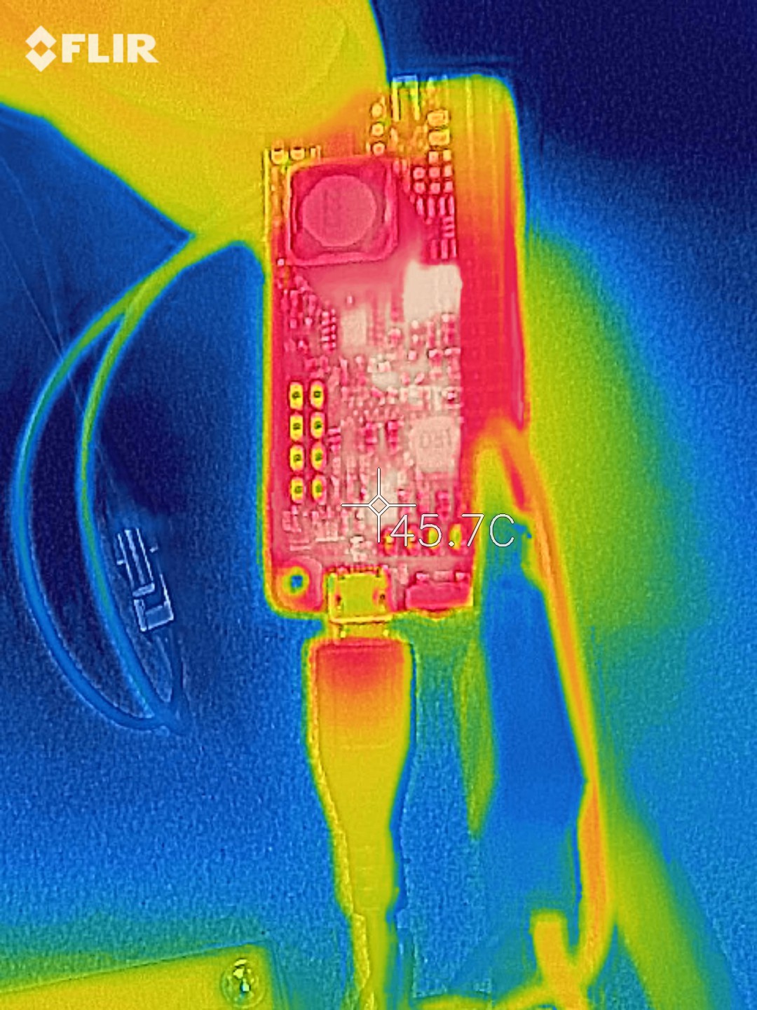
01/13/2018 at 00:21 • 1 commentI had expected my new FLIR ONE Pro to arrive next week, but I already received it yesterday. Nice!
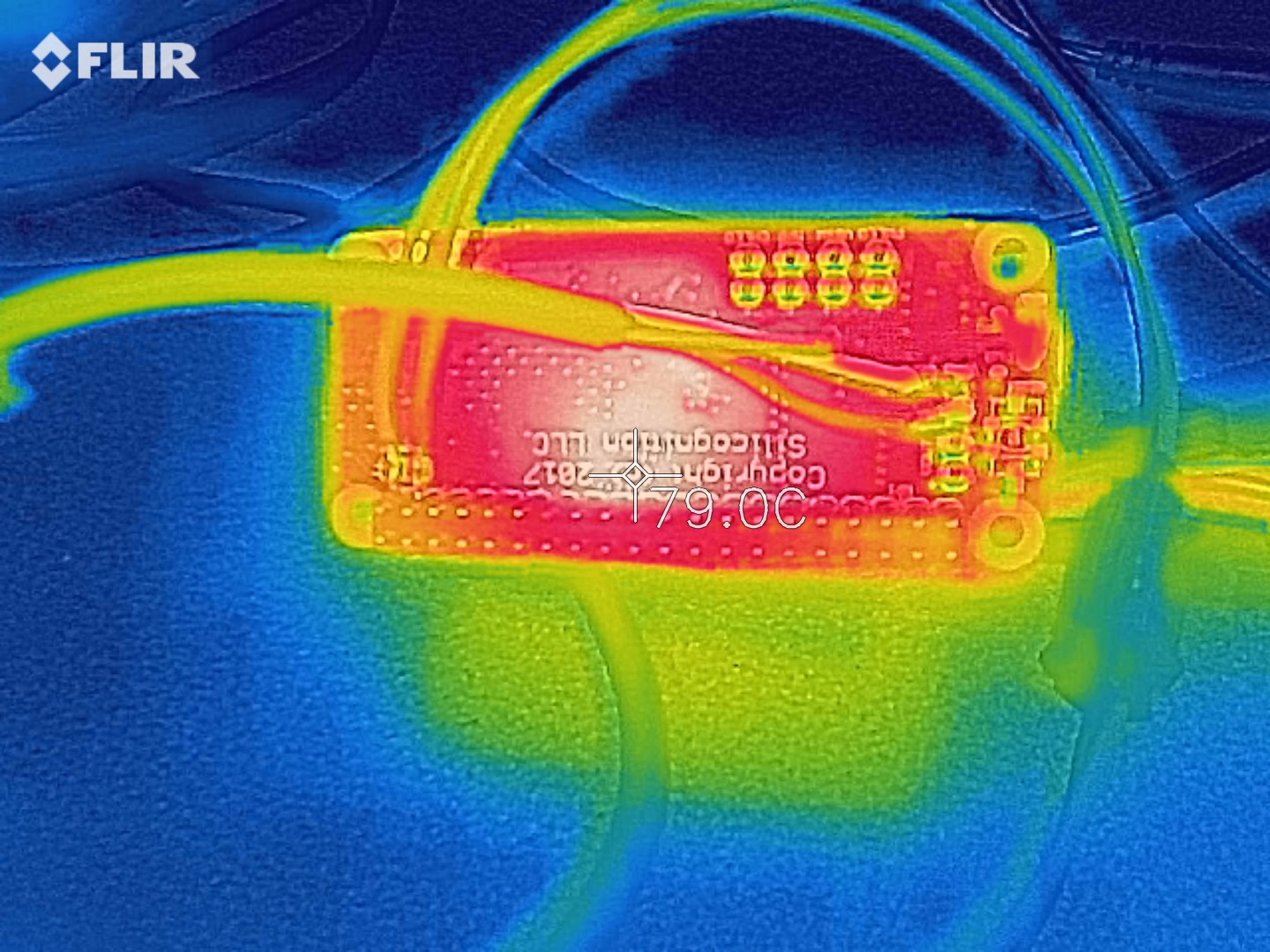
So here are some thermal images of my test unit under different loads. You may note that this is the LiFePO4wered/Pi+ version with the battery holder PCB area removed and an external battery connected by leads. That's the worst case for thermal performance as the PCB is the smallest and provides less heat sinking.
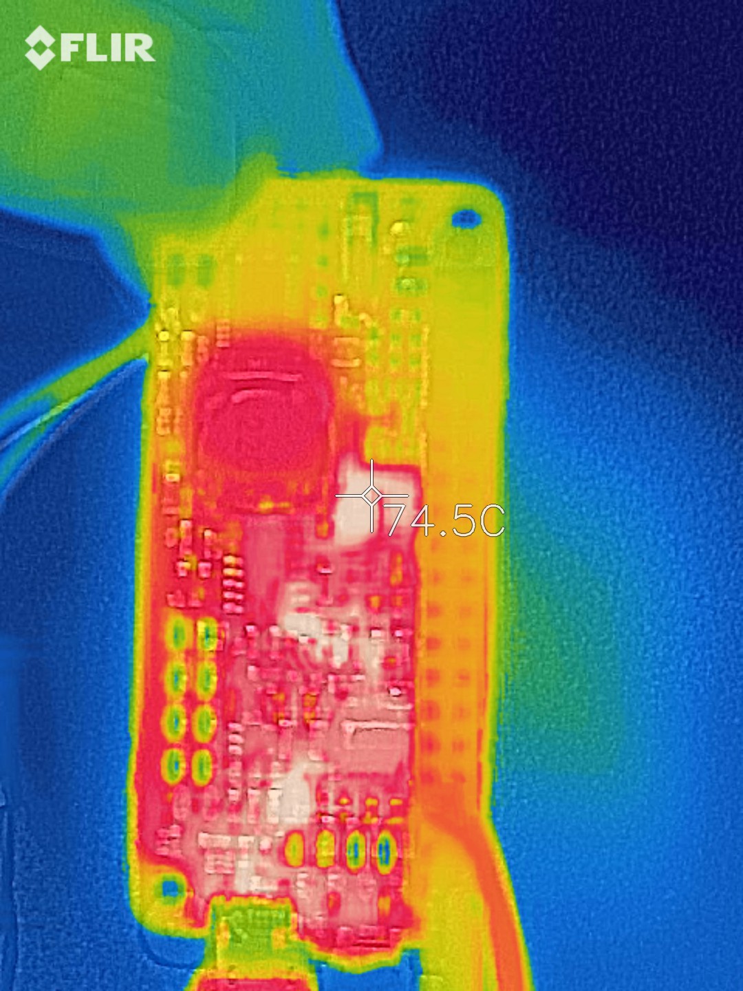
I had been running the test unit overnight with a load current of 1.5A powered by a 20V charger, so that's the first set of images I took:
![]()
![]()
Running at a high input voltage, the charger's power MOSFET and Schottky diode are of course the hot spot. But the hot spot is 20°C cooler at the same load current as my previous prototypes actually--a nice improvement!
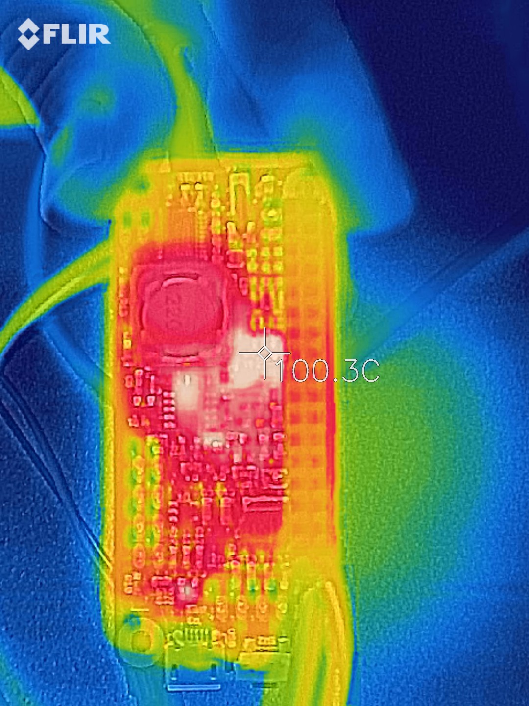
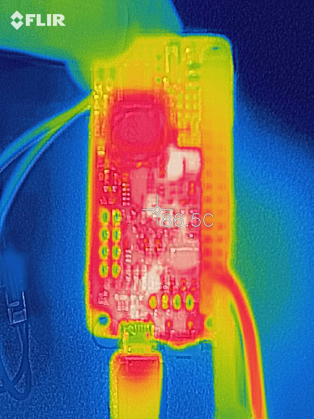
Let's crank the load current up to 2A:
![]()
![]()
Getting pretty hot, but nothing is going on fire. :) Just a little over the temperature reached by my previous prototypes when under only 1.5A load. Remember, this is without any cooling or heat sink, and I will definitely recommend active cooling when using the device under high load with a high input voltage.
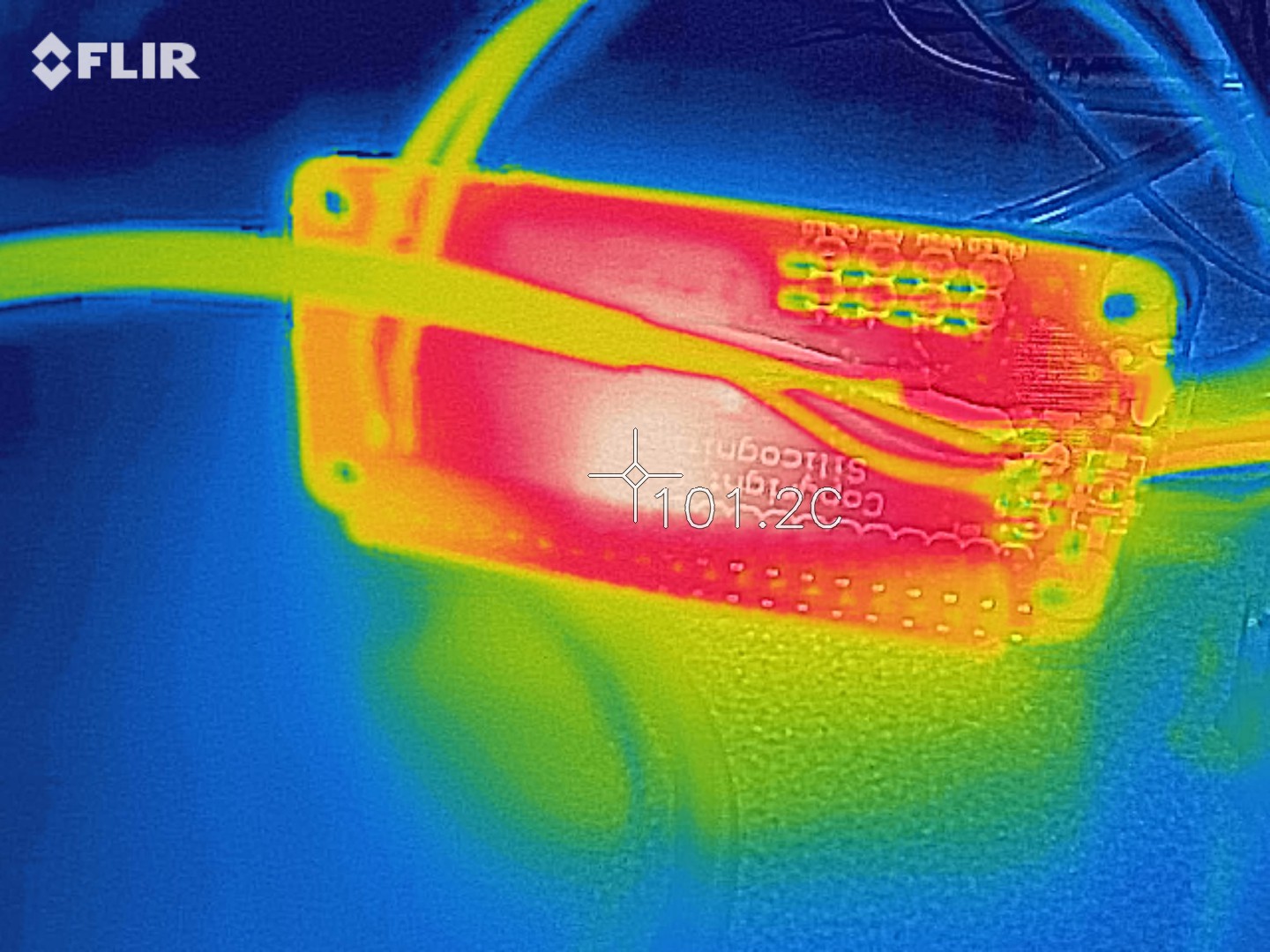
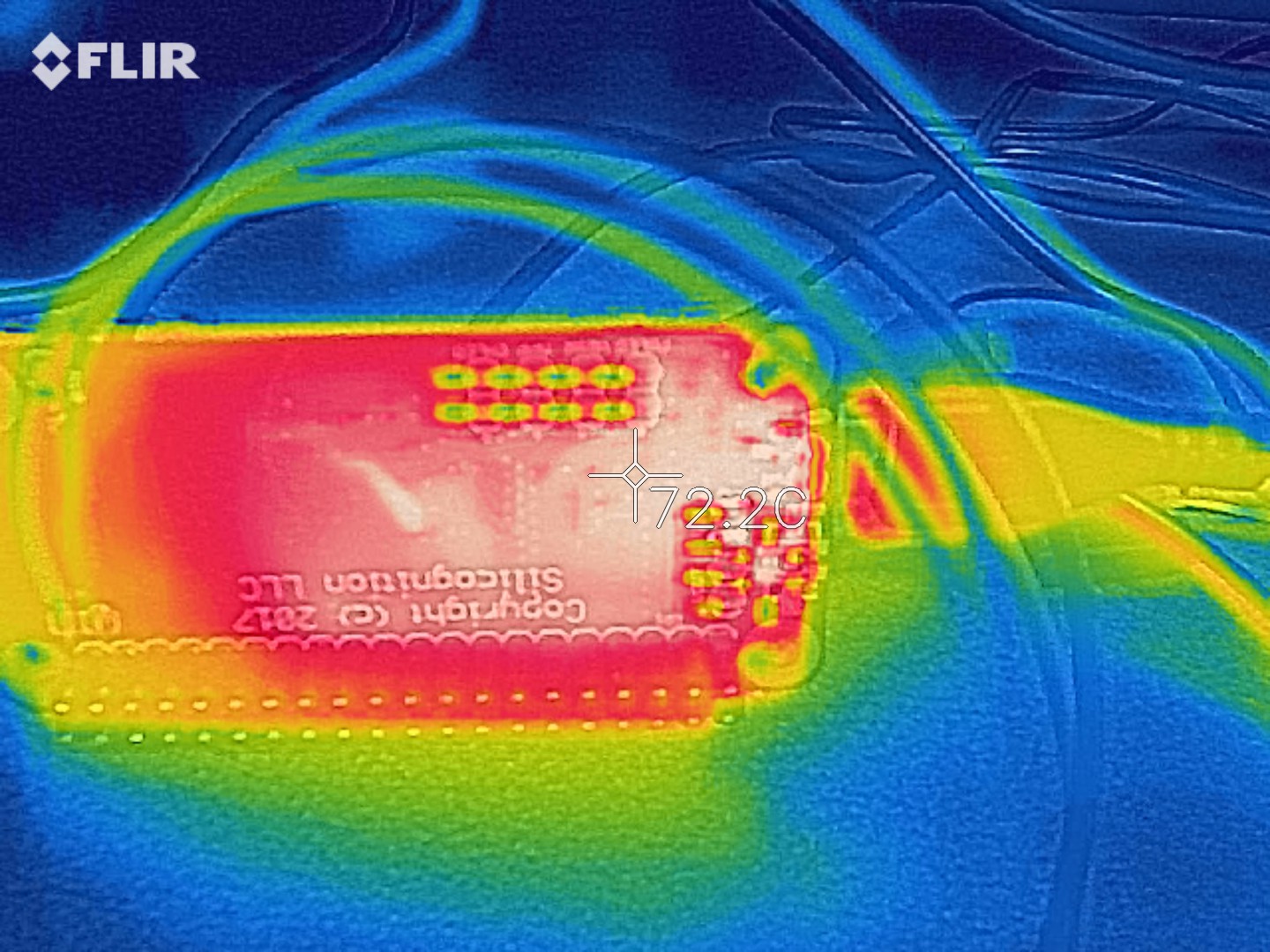
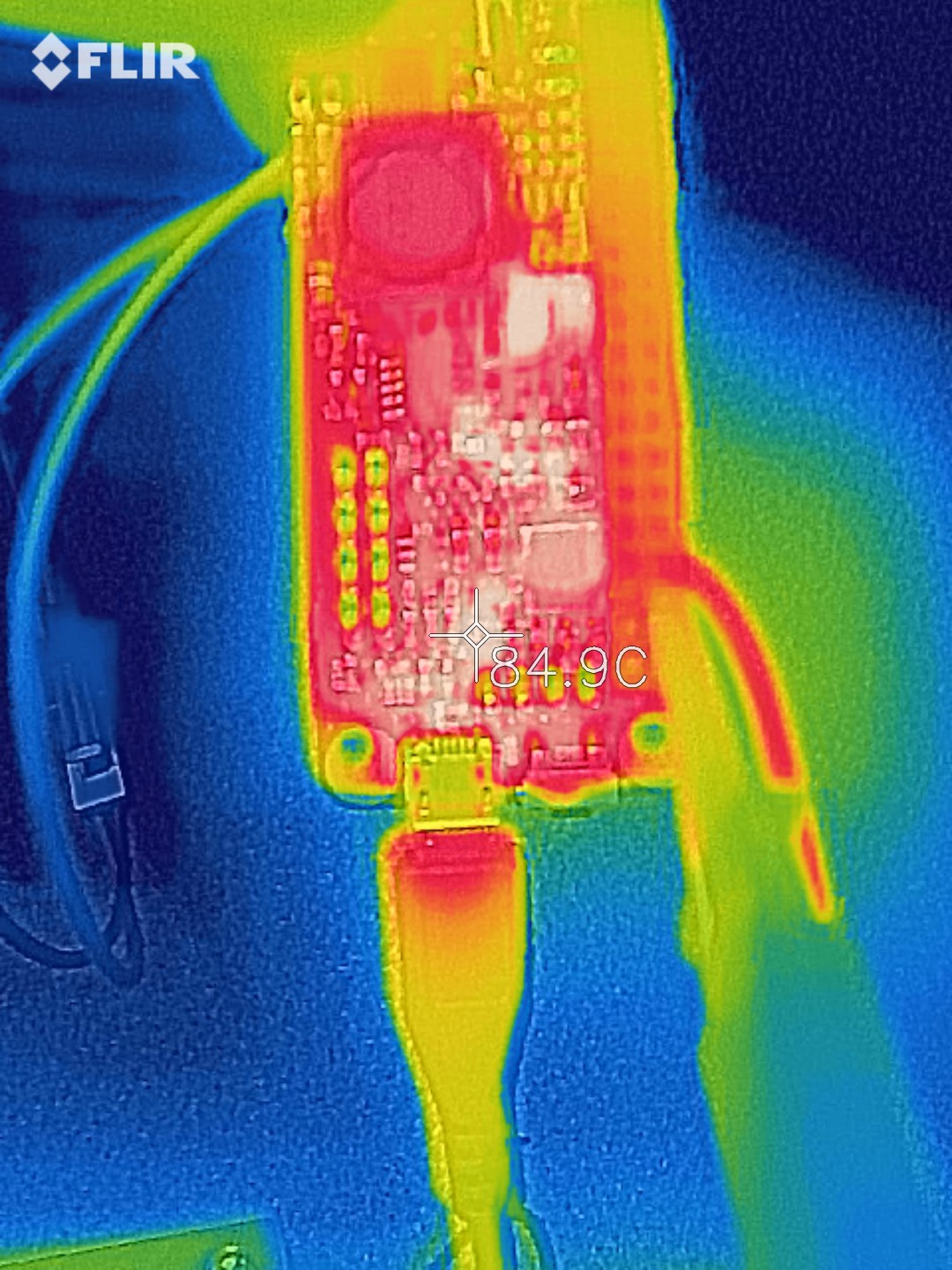
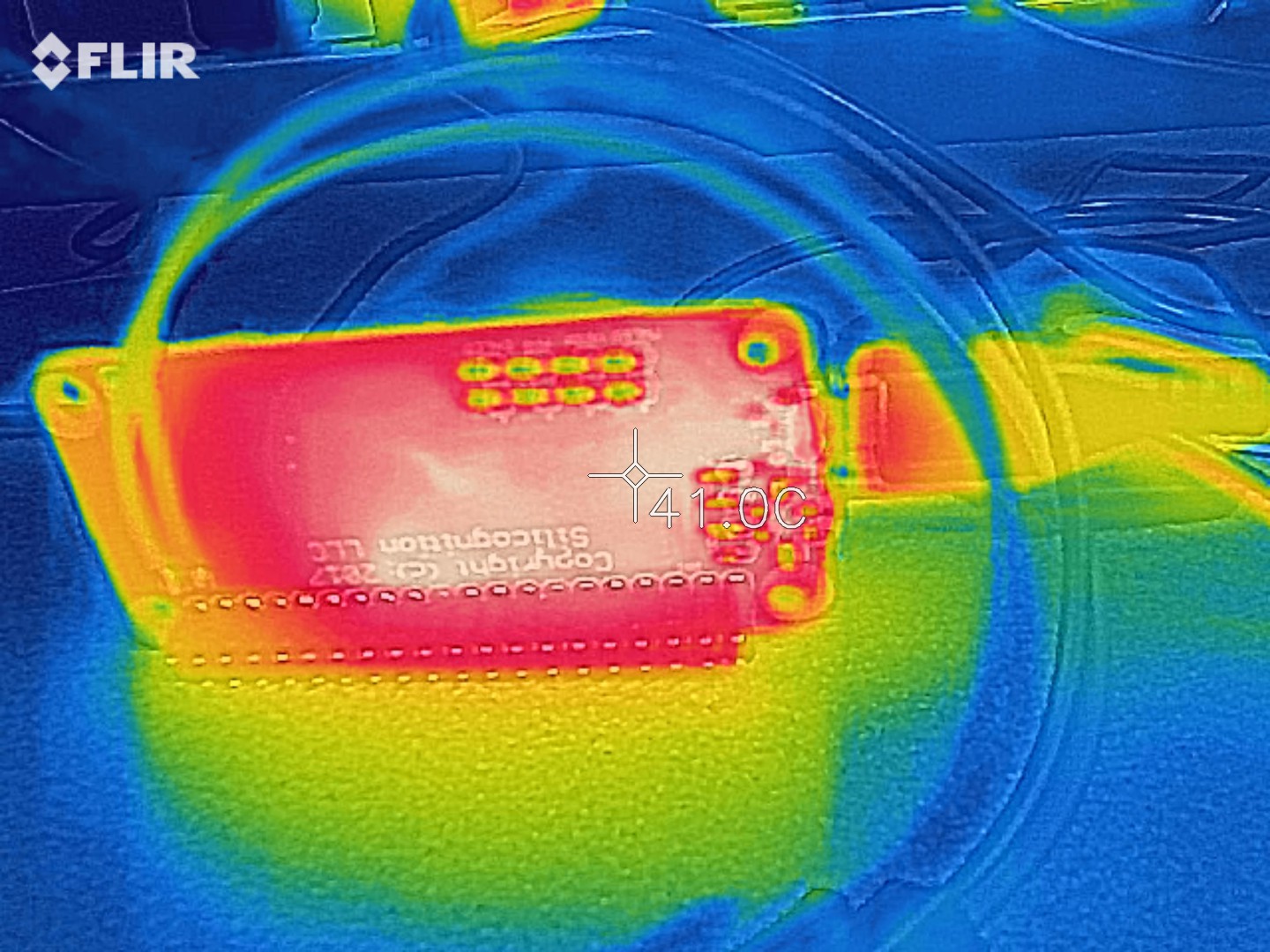
I then switched back to testing with a regular 5V USB charger on the input. I decided to do the 2A (worst case) test first:
![]()
![]()
![]()
![]()
Nice, no extreme heat anywhere! The hottest parts are the SSM3J338R pass transistor and the TPS61236P boost converter. At the lower input voltage, the charger switching stage is not so hot anymore. At this load, dumping 10W into the Pi, I'm pretty certain a well designed system is going to have a fan somewhere to cool things down. But I'm happy to declare that the LiFePO4wered/Pi+ will work as a UPS with 2A load at room temperature without active cooling! :)
But, it still looks pretty hot, doesn't it? Yes, but most people will never have to worry about this kind of load. A Pi 3 running at 100% CPU on all 4 cores only consumes about 800mA. That's 4W, and I have now proven the LiFePO4wered/Pi+ will handle 10W without active cooling. So I hope that will satisfy all the people wanting to power screens, hard drives, SSDs, SDRs etc. from my poor little UPS. :)
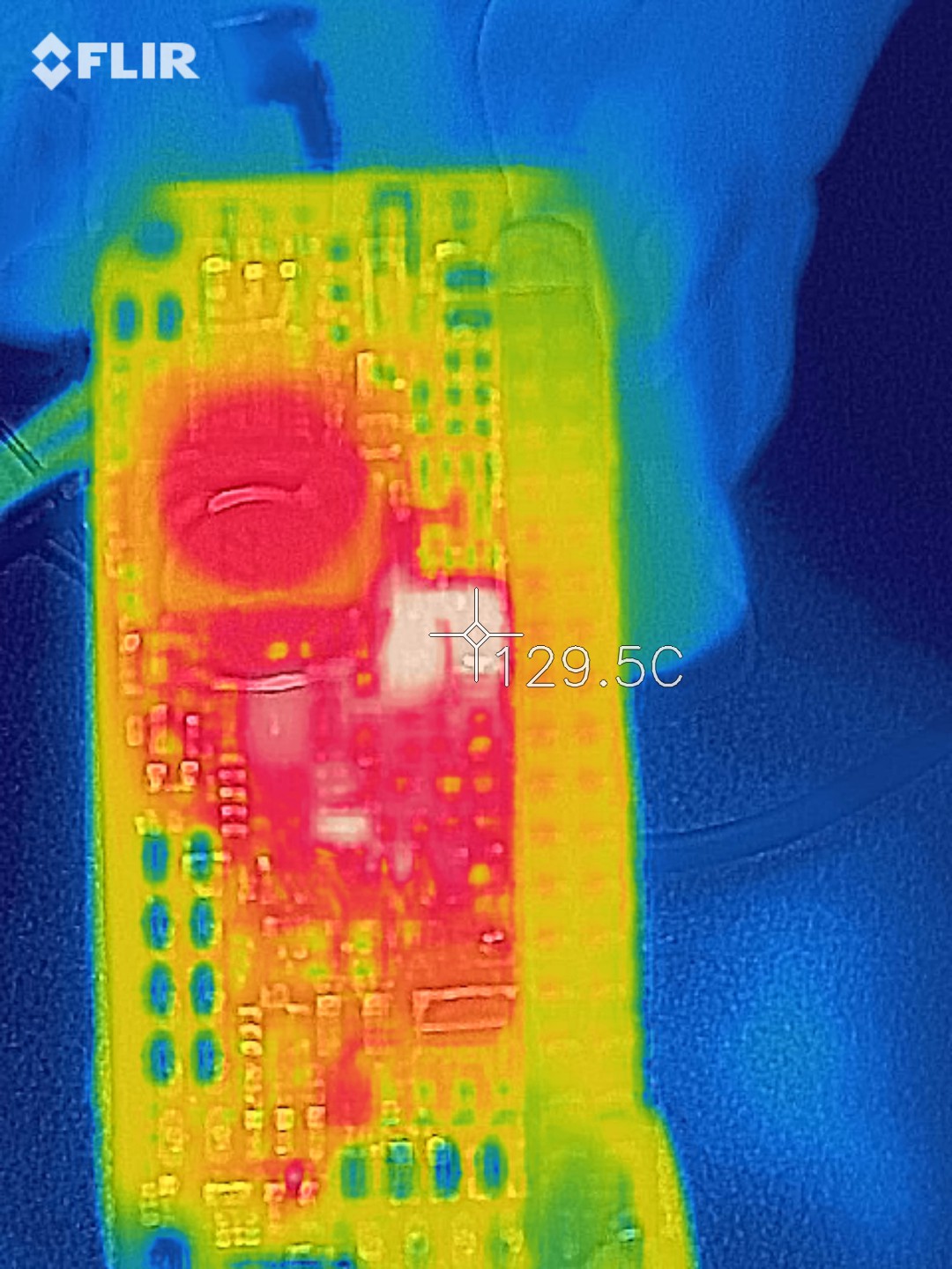
To give you an idea of how the system performs when under a "light load" of 1A (= a Pi 3 running full boar):
![]()
![]()
Hah! Hardly batting an eye.
So I'm calling this PCB revision "approved", on to production!
-
Last prototypes!
01/11/2018 at 23:36 • 0 commentsSo I built my prototypes last week and I have been testing them since, I just hadn't found the time to write about it yet. ;) Here are some shots of the build process, first pasted with components:
![]()
And out of the reflow oven:
![]()
This is how it looks all built up and with a 18650 battery and installed on a Pi:
![]()
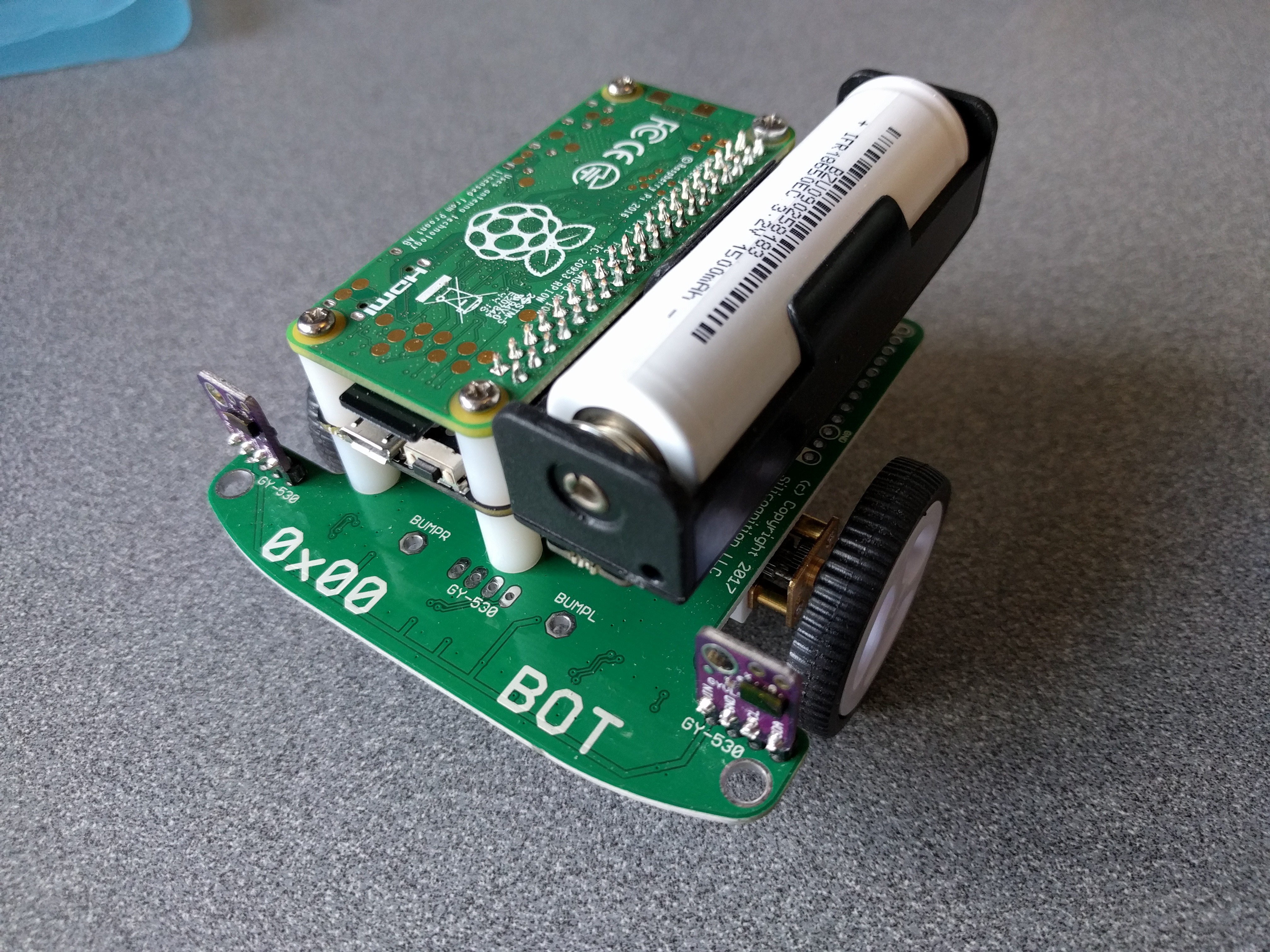
As you can see, there is accommodation for both 18650 and 14500 size batteries, and there are two positions for each size battery holder: one to be as compact as possible (battery close to the Pi) and one that provides a little distance to allow installation in standard cases while having the battery outside, as in this example with a 14500 cell in the official Pi case:
![]()
The case only needed minor modification to fit. Of course without making a hole, the USB connector and power button aren't accessible. But it's easy enough to make a hole and if you don't want to, you can enable auto boot / auto shutdown and solder input power to the Vin pads.
I started "easy" on the testing and everything was working great. Even with a Pi 3 running with 4 cores at 100%, things hardly got warm. Power down current, while keeping RTC, is still only around 4uA.
Then I pulled out my electronic load and started testing at 2A load current. The new switching MOSFET seemed to be handling it well, but oddly the pass transistor that previously wasn't giving me any trouble was getting really hot! Then I looked at it a little closer:
![]()
The device on the right was the one that was in the board and that I had sourced from China. The one on the left was bought earlier from a US distributor. The real part has a bigger body (probably to fit a bigger chip inside), and the leads come out flat on the bottom for less resistance and better heat transfer. The fake part looks like a normal SOT23. I really should have spotted that during assembly. Turns out the fake part works as a "power MOSFET" as well, but it has an RdsON of about 130 mohm, while the genuine part has an RdsON of 20 mohm or less. So it was burning way too much power at 2A load (2A load at 5V means over 4A from the battery do to the lower voltage and losses in conversion).
So I replaced the fake parts with real ones and the overheating went away. I have been doing high load testing since then and can confirm that the heat dissipation is low enough to allow UPS operation at 2A load current without active cooling! But it's close, I can't get much higher before the boost converter kills the output because of thermal protection, and probably inside a case it will overheat sooner.
But seriously, if you're building a system that is going to make a Pi burn 10W, you better have some fans for active cooling! :)
I also tried what would happen at higher currents with active cooling:
This ran for quite a while (several hours) at 2.5A load, eventually the boost converter did a thermal shutdown. I haven't determined the limit since it doesn't matter: the spec is 2A.
Also, remember my infamous project log where I burned up a transistor while testing at 20V input voltage? Well, I've been testing this for over 8 hours now and it's working beautifully. Yes, it gets hot, but no thermal shutdown, and nothing that some active cooling can't handle.
If you're wondering why there aren't pretty thermal pictures in here, it's because I don't have convenient access right now. Next week I should be getting my own thermal camera and then I'll be able to get some real data. :) I'm pretty confident in the design though, so I'm ordering production panels.
-
PCB and firmware update
12/15/2017 at 19:21 • 0 commentsI got my new proto PCBs from OSH Park, 0.8mm 2oz copper this time:
![]()
![]()
It has the improvements described in the previous project log, you can see the new DFN power MOSFET footprint for instance. I was getting ready to populate some prototypes by updating the BOM, until I noticed I had the wrong power MOSFET!
That AON7408 I talked about last time? Well turns out it's an N-channel MOSFET, and I need P-channel. How I ever missed that while tearing apart the datasheet, I don't know. So, I decided to use an Infineon BSZ120P03NS3 instead. It's more expensive, but the safe operating area looks even better:
![]()
Since I'm ordering production quantities to save time, I think this MOSFET should definitely have enough margin to work at high input voltages.
On the firmware front, a LOT of work has been done. I mean a TON. Unfortunately most time has been spent chasing an elusive bug. I think I finally got to the bottom of it. Although it's more a patch than a root cause solution, it's as good as it will get, since the bug seems to be related to a hardware limitation.
I really don't like the I2C peripheral in the small MSP430G micros I'm using. Calling it a hardware I2C peripheral is an overstatement, it's more like a glorified shift register. At every I2C related event, it requires software assistance. 8 bits are received: interrupt, set up for sending ACK. 1 bit sent: interrupt, set up for receiving 8. Start condition, stop condition: all handled in software. It stinks.
So when I needed to add shadow buffering to ensure the 4-byte RTC would be written atomically, I seem to have upset a delicate timing balance. Something in the timing was screwed up so sporadically the end of one packet and beginning of another would not be detected, causing the 8-bit I2C address with r/w bit and some other bytes (usually 0xFF because of reading) to be written over registers. Registers such as the LED state (not good) or the I2C address (very bad) would be overwritten, with symptoms ranging from a flashing LED to killing communication.
I tried for weeks, even months to track this down and fix it, but I think I just can't make it 100% reliable with this hardware. With the shadow buffering added, there's just too much code running and based on when different other interrupts (timers, ADC) end up running, I can't guarantee the I2C baby sitting code will always run on time. This is of course compounded by the fact that the Raspberry Pi has a retarded I2C peripheral as well that pays no attention whatsoever to I2C clock stretching, but just barges on even if the peripheral can't keep up.
So I did the next best thing: I implemented a patch to prevent stray writes to I2C registers. After the register to be written is received, the LiFePO4wered/Pi+ now expects an "unlock code" that is a combination of the I2C address, a magic value and the register to be written. Once this is received correctly, the other bytes are written. It just requires a small update to the host driver code.
Other firmware updates: boot and shutdown timeouts, 32kHz crystal timers, RTC code, higher resolution oversampled ADC values, touch timing fixes, 10-second button hold to force off. Many of these improvements will also carry over to the #LiFePO4wered/Pi as well, except those requiring a 32kHz crystal.
LiFePO4wered/Pi+
Next Gen LiFePO4 battery / UPS / power manager for Raspberry Pi, ideal for headless and IoT use
 As you can see, the case comes with a hole for a
  The result is a nice, solid feeling and compact "computing brick" for having a Pi-on-the-go:
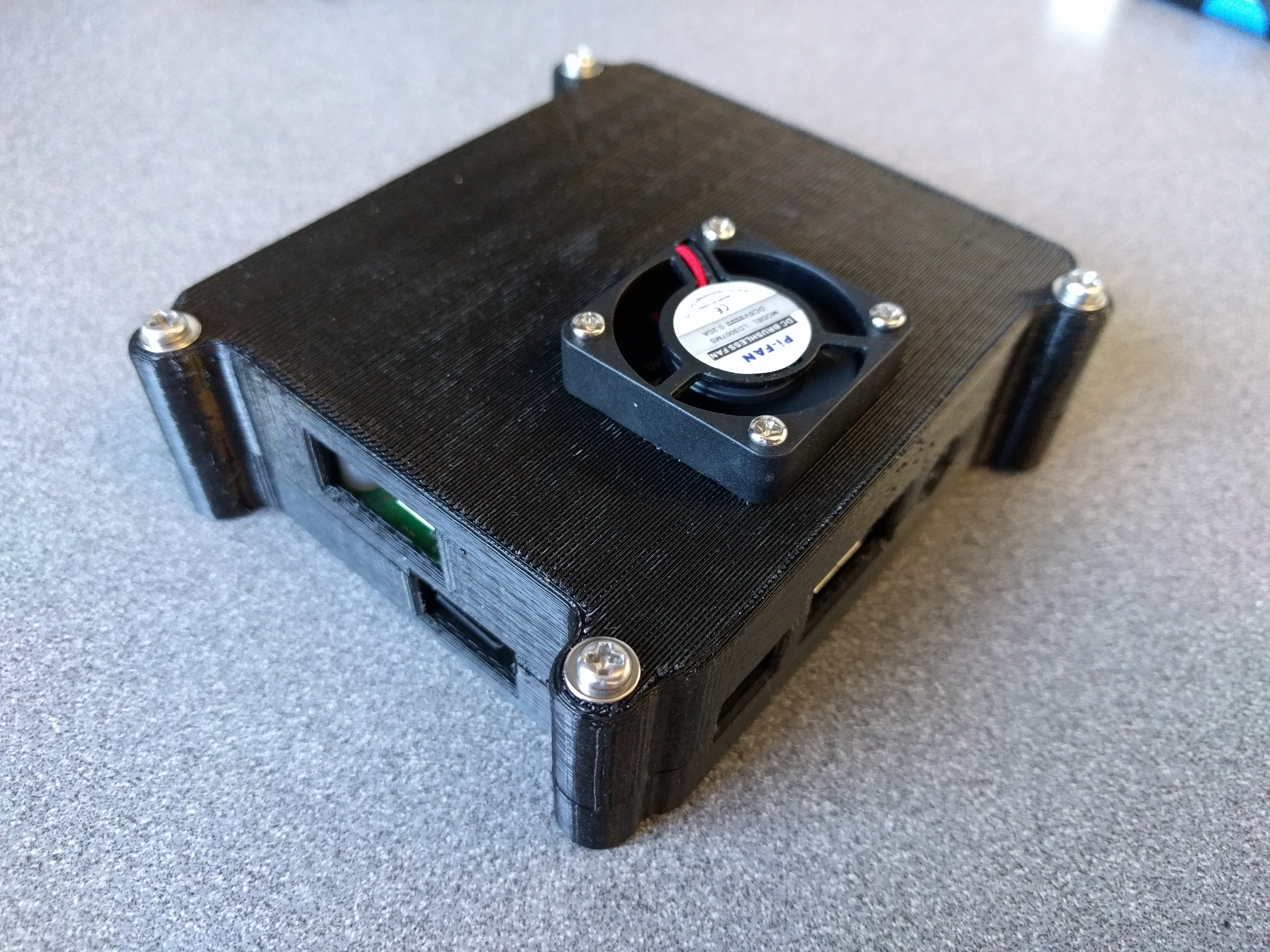 Because of the active cooling, the system stays nice and cool even under high load. With a Raspberry Pi 3 B+ running with 4 cores at 100% (load average 4.0), the core temperature of the CPU stayed around 62°C!