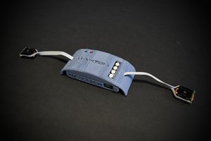
A retropie based gaming console
To make the experience fit your profile, pick a username and tell us what interests you.
We found and based on your interests.
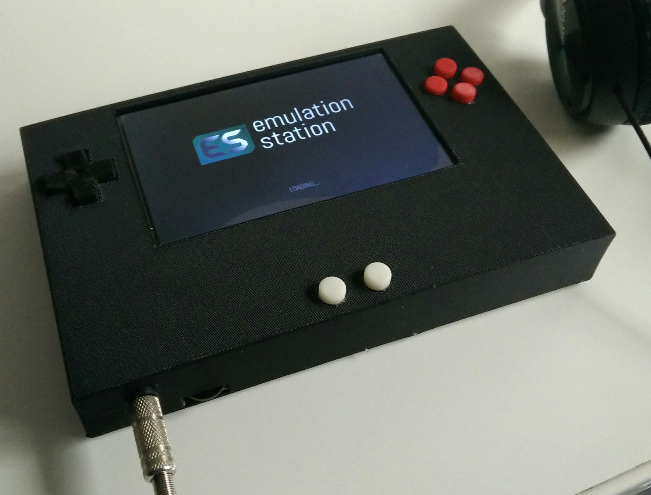
I moved component into a new version of the 3d case, printed last week.
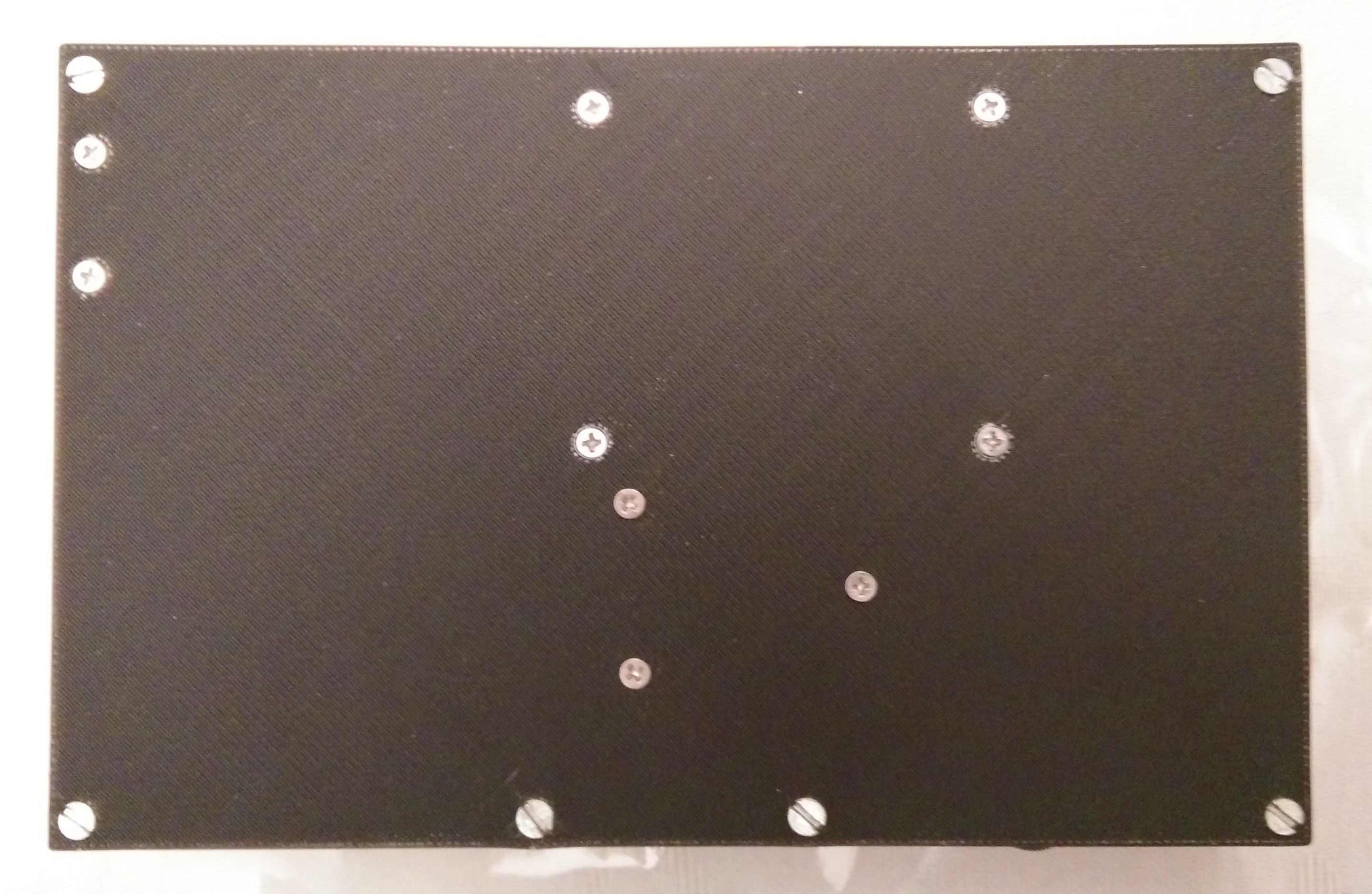
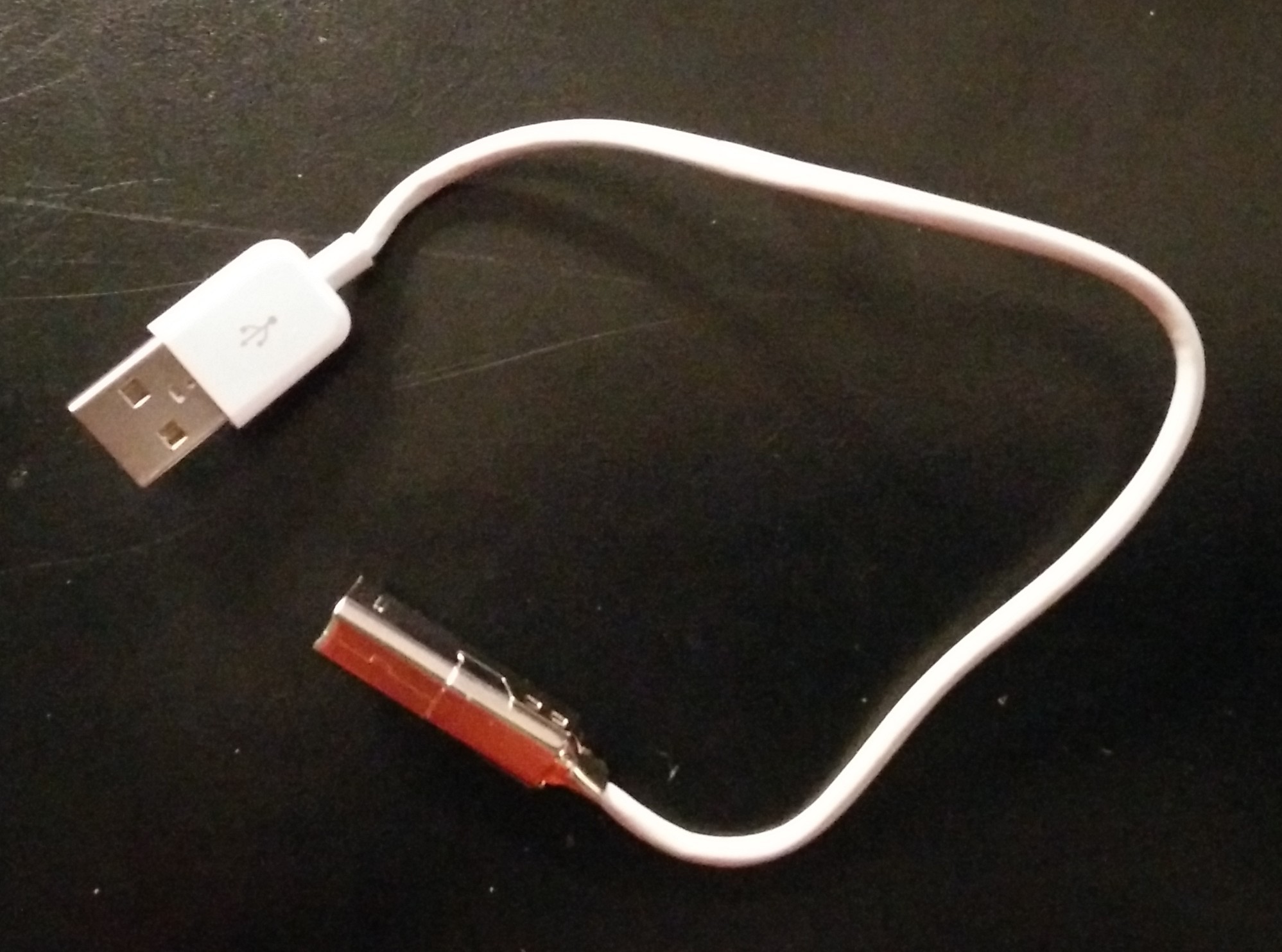
I moved the USB charging circuit to top right (so you can play while charging) and added 2 more screws holding the bottom of the case and 1 on the top of the case.
It works but there is an issue with sound : left and right channel are kind of mixed, so it’s not really stereo.
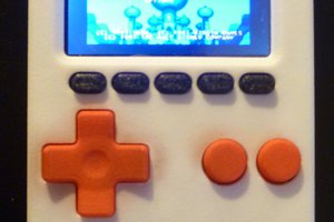
The project is almost finished. The case is closed, everything is connected, except top left & right buttons.
It is functional and kids are loving it.
However, there’s still room for improvement : battery holder are too thin, and buttons are a little flacky (the way they are hold is not optimal).
Mainly, it’s the case which need some adjustment.
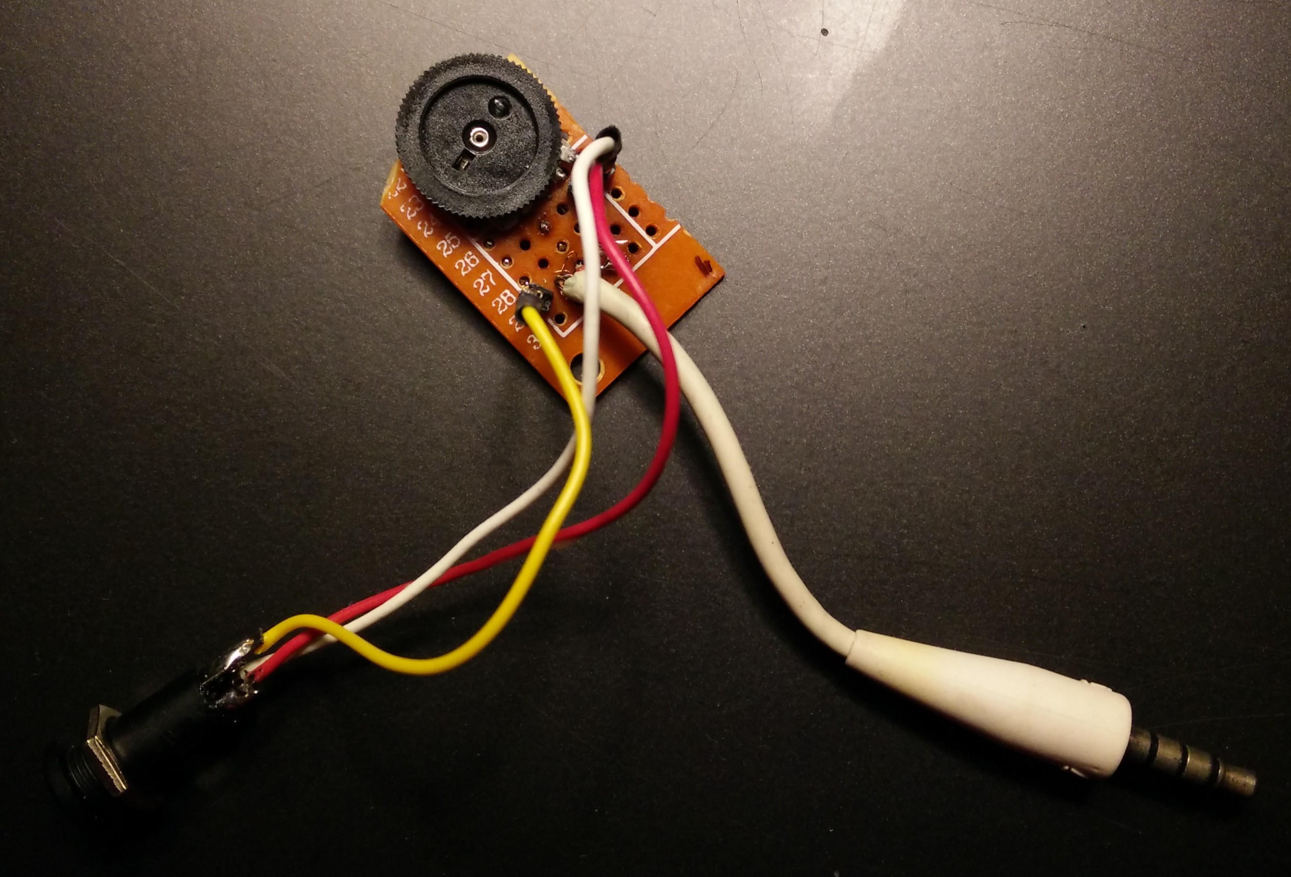
The audio circuit is here to adjust audio from Rasbperry Pi using a B503 potentiometer.
You can find the layout on that amazon comments from driftinge30.


I’m designing the box to be 3d printed.
Work is in progress on github : https://github.com/paulgreg/retropie-portable-gamegear/
and follow Adafruit’s procedure: https://learn.adafruit.com/adafruit-dpi-display-kippah-ttl-tft/installation
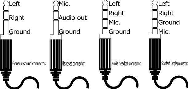
Here is the layout for the jack connector :

And here’s the layout from the potentiometer from a review on https://www.amazon.co.uk/16x2mm-Double-Taper-Duplex-Potentiometer/dp/B00O9Y6Z70 : The pin layout (wheel down and pins facing up) far left-ground, (call it pin 1) from the far left pin 1-ground. moving right is 2-right input, 3 left input, 4-left output, 5 right output. 5=far right side pin.
Download and install latest version of retropie on a 8 Gb (at least) micro sdcard.
Create an account to leave a comment. Already have an account? Log In.
Become a member to follow this project and never miss any updates
About Us Contact Hackaday.io Give Feedback Terms of Use Privacy Policy Hackaday API Do not sell or share my personal information