I made a presentation on how laser prism scanning might use Bessel like beams. I outline how they are created and how they might be used in combination with laser prism scanning. This due to recent interest to startups like Inphocal.
- I claim the use of two lenses which in combination focus light into a structured optical beam. Between these lenses there is a prism which can rotate so that a scanline can be formed. The first lens focuses the light parallel to the scanline and the second lens focuses the light orthogonal to the scanline.
Claim 2:
- The optical system of claim one, wherein the focal length of both lenses are different such that they circularize the light source.
Claim 3:
- The optical system of claim one, wherein each of these lenses is similar to an axicon. The difference with a normal axicon, is that each individual axicon focuses the light in one dimension and not two as a normal axicon. The light is just propagated and not diverted along the other axis.
Only the combination focuses the light along two axes, one orthogonal and one parallel to the scanline.
In the laser prism scanner, so far Gaussian beams are used. An alternative would be to use a Bessel beam. An advantage of a Bessel beam is that they have a longer depth of field as compared to a Gaussian beams for a given focus size. A true Bessel beam is non diffracting. True Bessel-beams are not possible as they require infinite energy. Bessel beams can be approximated and then called structured light. These structured light beams are less diffractive than Gaussian beams.
A Gaussian beam is created by focusing light into a point. Structured light is created by focusing light along a line. This is denoted by Bessel beam in the figure below.
Recently, companies such as ASML, Europe's most valuable tech firm according to BBC, started to support laserscan startups such as Inphocal which use structured light. Inphocal is based on intellectual property from Cern (WO2019211391A1)
Inphocal received funding from HighTechXL, NWO, DeeptechXL and the European Union.
CERNs contributions to Kicad are highly appreciated. WO2019211391A1 feels incomplete.
In short it outlines an improved version of the axicon. This new lens produces a beam which better approximates a Bessel beam and diffracts less.
I can understand this due to the greater design freedom as the shape seems mathematically more general to me, but still I would be interested to see the actual differences backed up by optical simulations. The authors from CERN do not provide this.
CERN furthermore does not really goes into the difficulties which arise by scanning a laser bundle. I can imagine Inphocal uses a galvo scanner from scanlabs and does not have a challenge with cross scan errors. Galvo scanner are slower than polygon scanners.
In specific, the authors do not outline how the movement orthogonal to the scanline can be mitigated if a Bessel beam is scanned by a prism. Given my experience with cylindrical lenses and Gaussian beams. I propose a similar solution for Bessel beams.
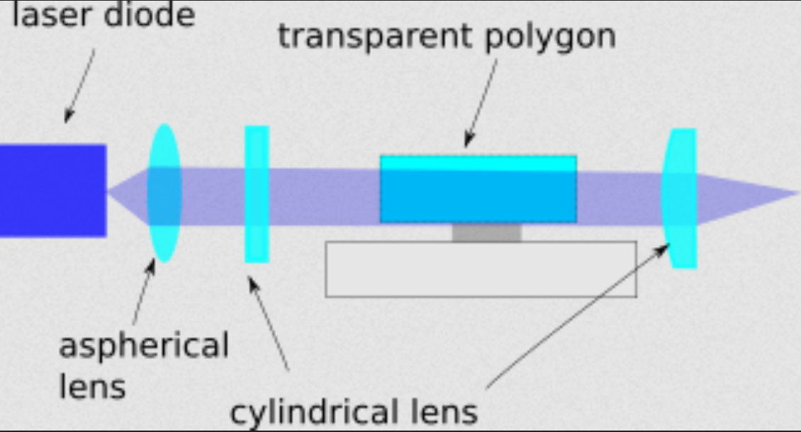
For Gaussian beams, my solution is outlined below;
Light diverges from a laser diode and is collimated by an aspherical lens. The first cylindrical lens focuses the light parallel to the scanline and the second cylinder lens focuses the light orthogonal to the scan lens. As the cylindrical lenses have a different focal length. The elliptical laser spot is circularized. Furthermore, the second lens removes part of the cross scan errors created by not mounting the prism orthogonal to the rotation axis.
Light will still be parallel after leaving the prism if the prism is perfect and as such be focused into the same point.
Perfect means here that opposing faces of the prism are perfectly parallel. If this where not the case and it would be tapered, the outgoing rays would not be parallel to the incoming rays of the prism.
Please recap what happens. You could focus the light directly after it leaves the aspherical lens as a collimated bundle.
The lens is split into two components and each component only focus along one axis. The light is not altered along the other axis by each component.
My bet is that this trick for Gaussian beams can also be repeated for Bessel beams.
For Bessel beams we repeat this trick, here the cylindrical lenses are replaced by a pair of axicons. The difference being that normal axicons focus light along two axes where i focus light along one axis, similar to the Gaussian beams.
Here again the focal length can be chosen so that the beam is circularized. If the first lens focuses light along the scanline and the second orthogonal to the scanline, part of the cross scan error can be removed.
This can again be repeated for the lens outlined by CERN in WO2019211391A1. This lens is split it into two lenses and a prism is placed between the lens. Again the beam can be circularized and the cross scan error can be removed. The patent from CERN is pending and its final claims uncertain. I added a presentation on the topic.
In the blog state of open source, Prusa complains about cheap 1:1 clones who do not honor the open source ethos and as remedy suggests altering the license.
The most successful companies, e.g. Microsoft and Apple, in the world are closed source. Still closed source seems not to work for a number of technologies; operating systems (Linux) and programming languages (Python). In the nature of the firm, Coase argues that the main reason to establish a firm is to avoid some of the transaction costs of using the price mechanism. Open source lowers the transaction costs for inbound innovation. Information is more readily available to outsiders and less asymmetric. As a result, the technology grows. I think open-source is best suited for "highly" complex products with an initial weak product market fit. It works better for software than hardware. As hardware is harder to reproduce. This leaves the question of monetization. Open source software is now monetized by cloud providers who earn money by running it in the cloud. Examples are Github, Amazon Web Services or DataBricks. It is also monetized by software developers who tailor the software for specific business needs. They enjoy large benefits by the fact it is open source. As they can simple hop companies and sell the same knowledge again. A problem with proprietary software is that the new firm or client of the developer would also require a license.
In your blog you also give an example of solar panels. One example for all is solar panels – the original inventions and processes were gradually copied by Chinese companies. After that, with the help of state subsidies and tax breaks, they drove all competition out of the market within a few years. Today, you have virtually no chance of buying a non-Chinese-made solar panel. I agree with your assessment that this makes solar panel manufacturing less profitable. It might also be a reason for a government to intervene using tariffs. Still, an entrepreneur can still make money. Once the solar panel becomes free, the challenges becomes getting it on your roof. You might also need advice on how to best place your solar panel. It is very hard for the Chinese to compete with a Dutch solar installation company given the fact they are in China. They can also not work in the Netherlands due to regulations. If China makes printers for free, you might need to alter your workforce or firm. I still see a lot of ways of making money.
Moving back to the Prusa firm. I would not alter your open source approach but better look at how it can provide unique value. Your company actually pursues a mixed strategy. Part is closed and part is open. It is impossible to make a firm a completely "open". I would not focus on changing the relation between Europe and China or the patent system. These things are external to your company and not under your control. You can make it easier for external parties to add new tools to your printer. You could give these external parties a slice of the profit. Goal here is to really think outside of the box and look at your relation with the customer. As example, there is a Dutch company called Swapfiets, who offers bikes via a subscription service instead of selling them. This has been hugely successful. I would not advice you to offer a subscription service. Still, it shows that the way you interact with the external parties can be a key differentiator. If you control the most popular design of the printer, you should still be able to make money simply as you decide which parts end up in the next printer. A successful open source approach, requires more thought than simply putting the source code on the web. This was done by Lulzbot and not successful.
Finally, I partly disagree with your view on patents. I believe like you and the Economist that the patent system is broken. From experience, I believe that most patent applications are a failure. Still, you should patent given the opportunity. If you have a lot of money, understand the boundaries of your innovation, have a good patent able innovation; you should patent. A patent might also be key in getting government support. In your case, you might not want to use your name as it destroys your image. You could still use a shell company and someone else his/her name. Some companies hide patents so they can strike their opponent by surprise. I currently lack the resources to do it. Filing patents is also very tricky. Still, I don't see how not patenting helps the world if you really see a good opportunity. If you want to change it, complain about it, use the power you have in a way which aligns with your views, but don't leave money or power on the table.
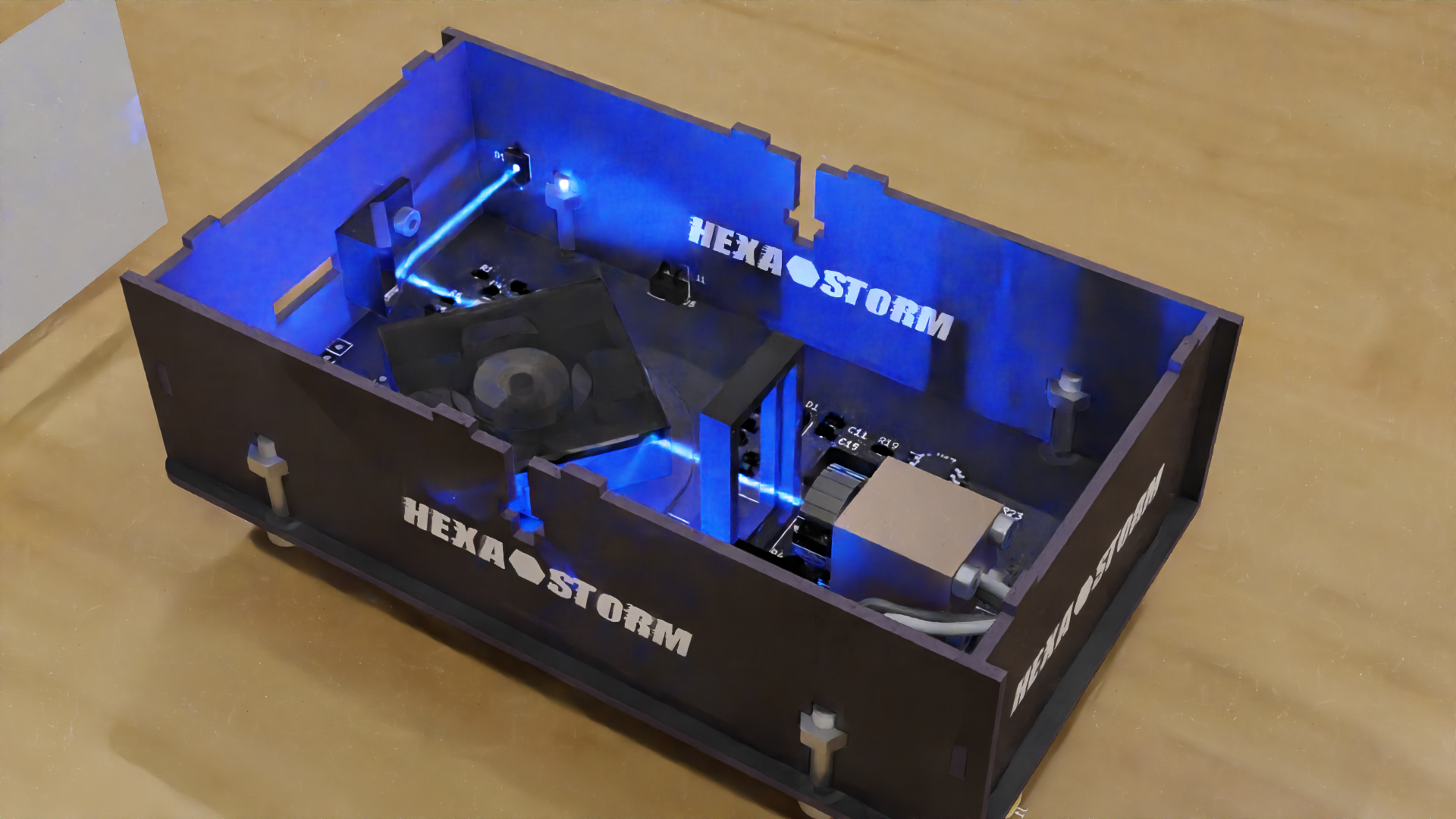
I reduced the pole length to 10 mm. I now end up with a cross scan error of 180 microns (60 pixels at 3 microns wide). The pattern is very constant over time and seems to be due to the prism. I measured seven prisms and arrived at an error ranging from 35 pixels to 45 pixels. The prism in this image had an error of 41 pixels. As a result, I think 19 pixels are due to "vibrations".
The camera distance to the prism is 36 mm (prism facet parallel to CCD chip and distance between prism and CCD chip). Note that this is very similar to my earlier measurement with the Ricoh motor (PCB motors suited for laser scanning). Here I arrived at 160 microns.
I did experiments with the new bearing. Results so far; - rotation can be achieved vertically; ferrite is added below the PCB. The magnets in the rotor are pulled toward the ferrite As such, the rotation axis does not have to be parallel with gravity. The motor is more than powerful enough to overcome the additional friction.
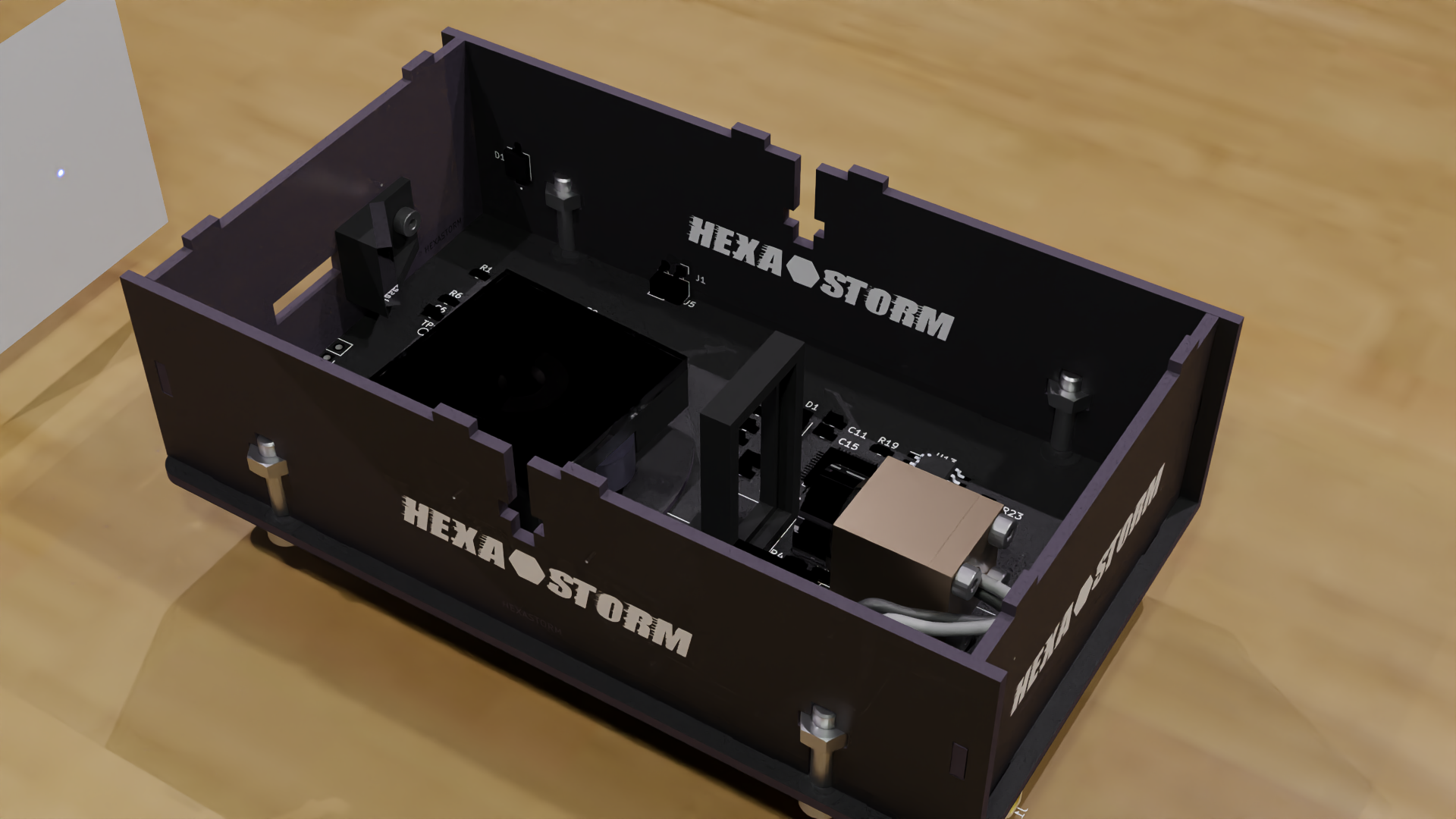
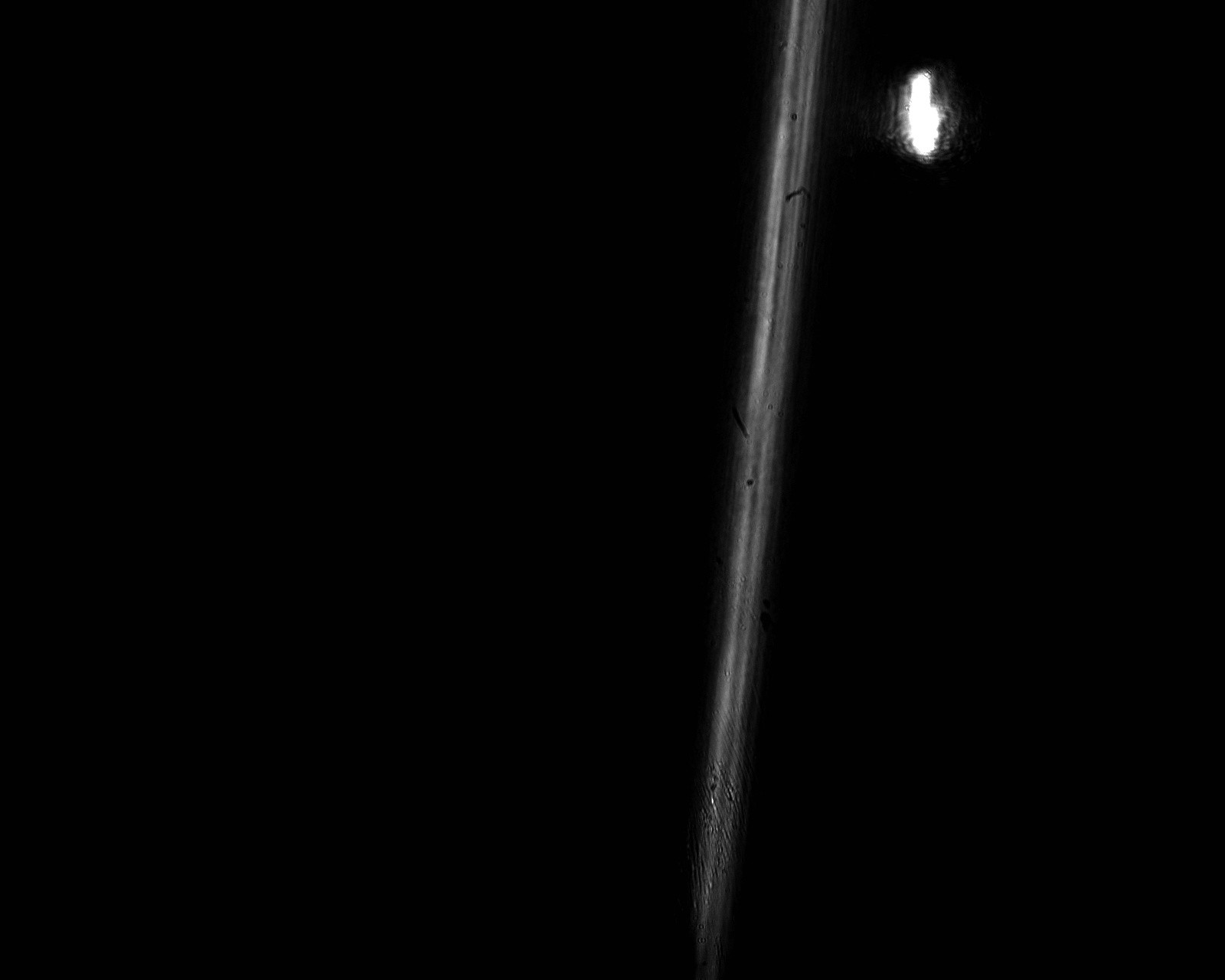
- on small time scales, i.e. less than 10 facets/lines, the cross scan error is low on longer time scales , i.e more than 30 facets. The cross scan error is high. For small time scales, the cross scan error seems good enough for exposure.
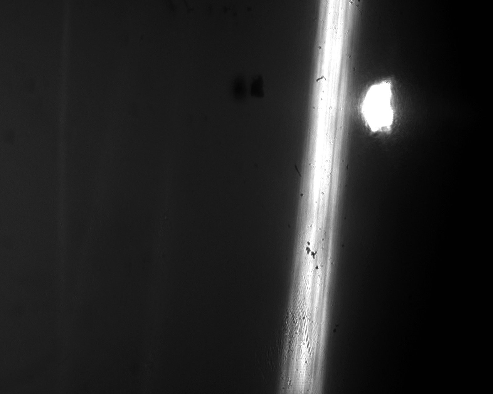
An image at a short time scale, i.e. less than 10 lines in image.
An image of a long time scale,
The spot on the side is as not all light is refracted through the prism or due to some internal reflection. This is easy to fix by either a slit or changing the thickness of the prism. As such it is disregarded.
From additional research, I conclude that you are indeed looking at a vibration. This vibration is likely due to particles or dusts between the axis and the bearing. I shortened the pole and still saw this behavior (see next blog). The noise removed after adding a bit lubricant.
This displacement and angular deflection are described by the following formula;
The centripetal force rises with the square of the speed. As such, I have two methods to test this theorem; - reduce the speed - decrease the beam length
Calculating the first natural frequency of the beam and see if this is in the time domain of 30 lines. I arrived at multiple kHz. Probably, the treatment is too simple.
Experimental notes: Speed around 1000-2000 RPM Length extracted is 13.75 mm Length used in this experiment 18.8 mm
I came up with a strategy to mount the rod onto the prism. A very viscous putty is placed between the rod and the prism which becomes very hard and green.
The rod hole tolerance is low and the prism rotates over its glass substrate. You might argue that some of the putty sticks out and this affects the rotation. I cut a small groove in the final version. Friction seems low, I will need to check measurements for the cross scan error. Most interesting would be to compare distorting coming from the prism facets with those coming from the bearing. In the figure below you see a quartz prism, a sinter bronze sliding bearing and green putty
In the figure below you see parts separated; Curing time is around an hour at 50 degrees. The vendor recommends not going over 40 degrees.
 Hexastorm
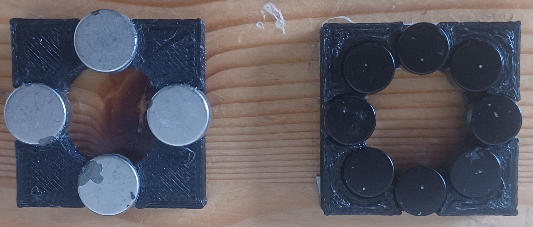
 Open source lowers the transaction costs for inbound innovation. Information is more readily available to outsiders and less asymmetric. As a result, the technology grows.
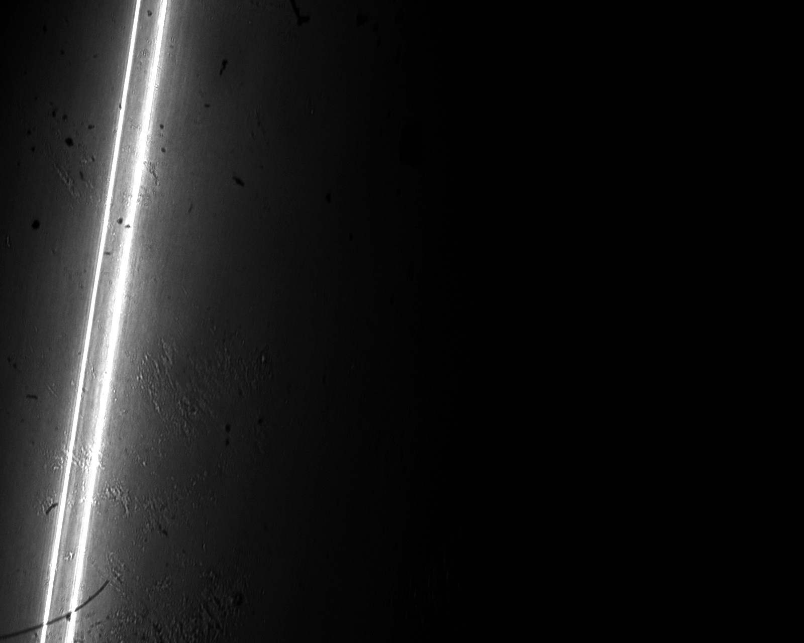
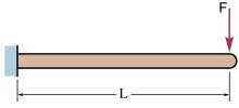 This displacement and angular deflection are described by the following formula;
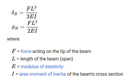 The centripetal force rises with the square of the speed. As such, I have two methods to test this theorem;
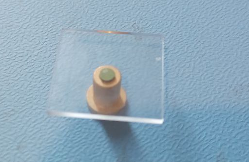 In the figure below you see parts separated;
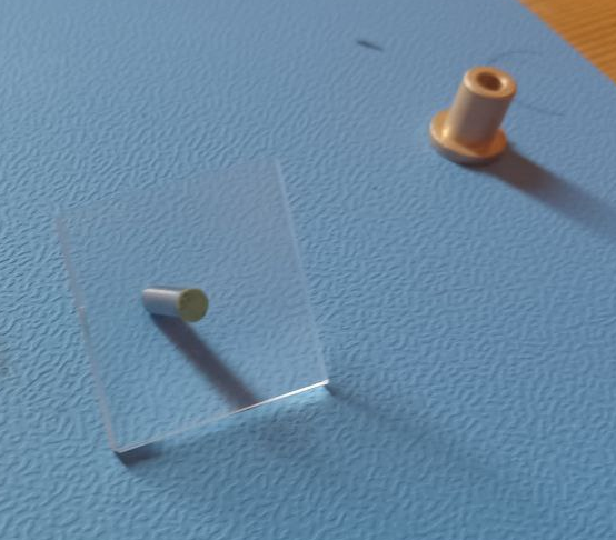 Curing time is around an hour at 50 degrees. The vendor recommends not going over 40 degrees.