 HP (@banjohat)
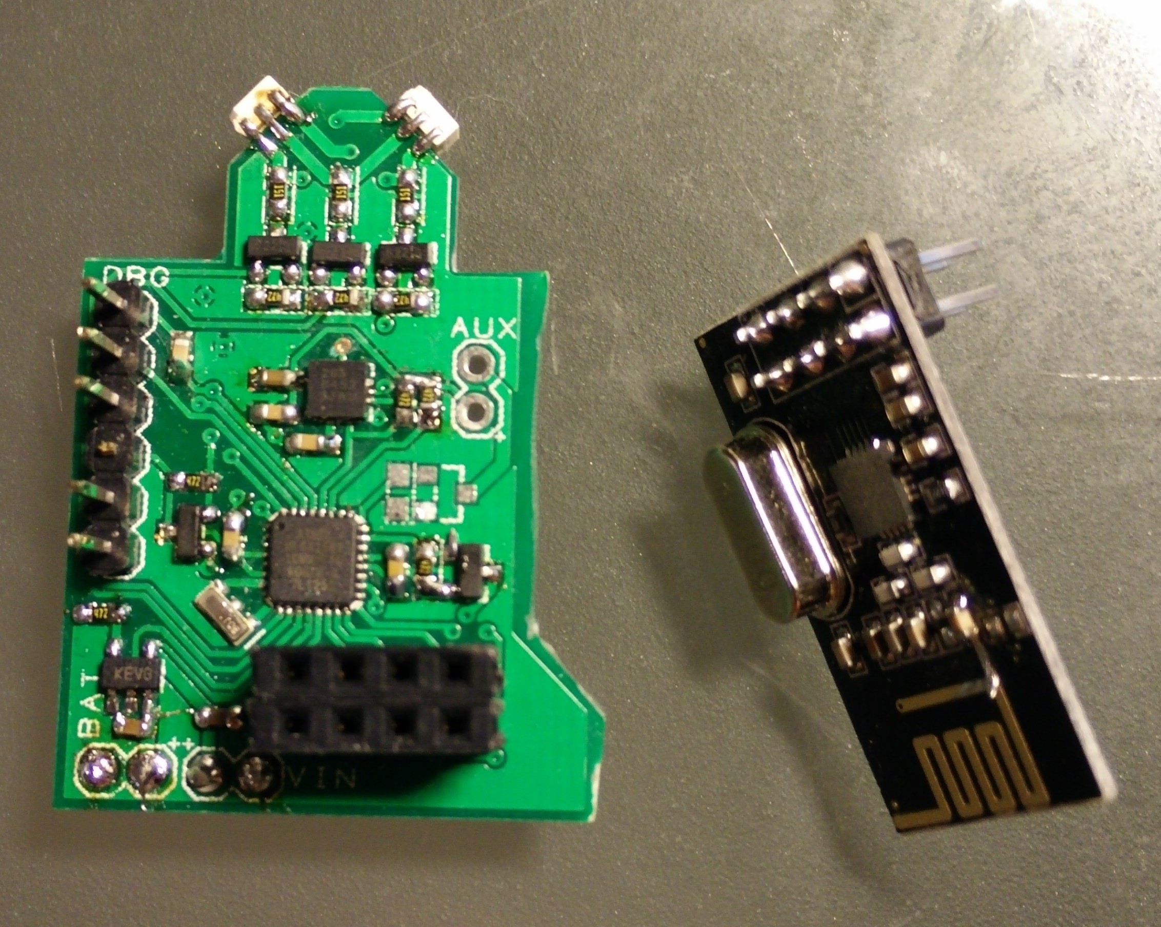
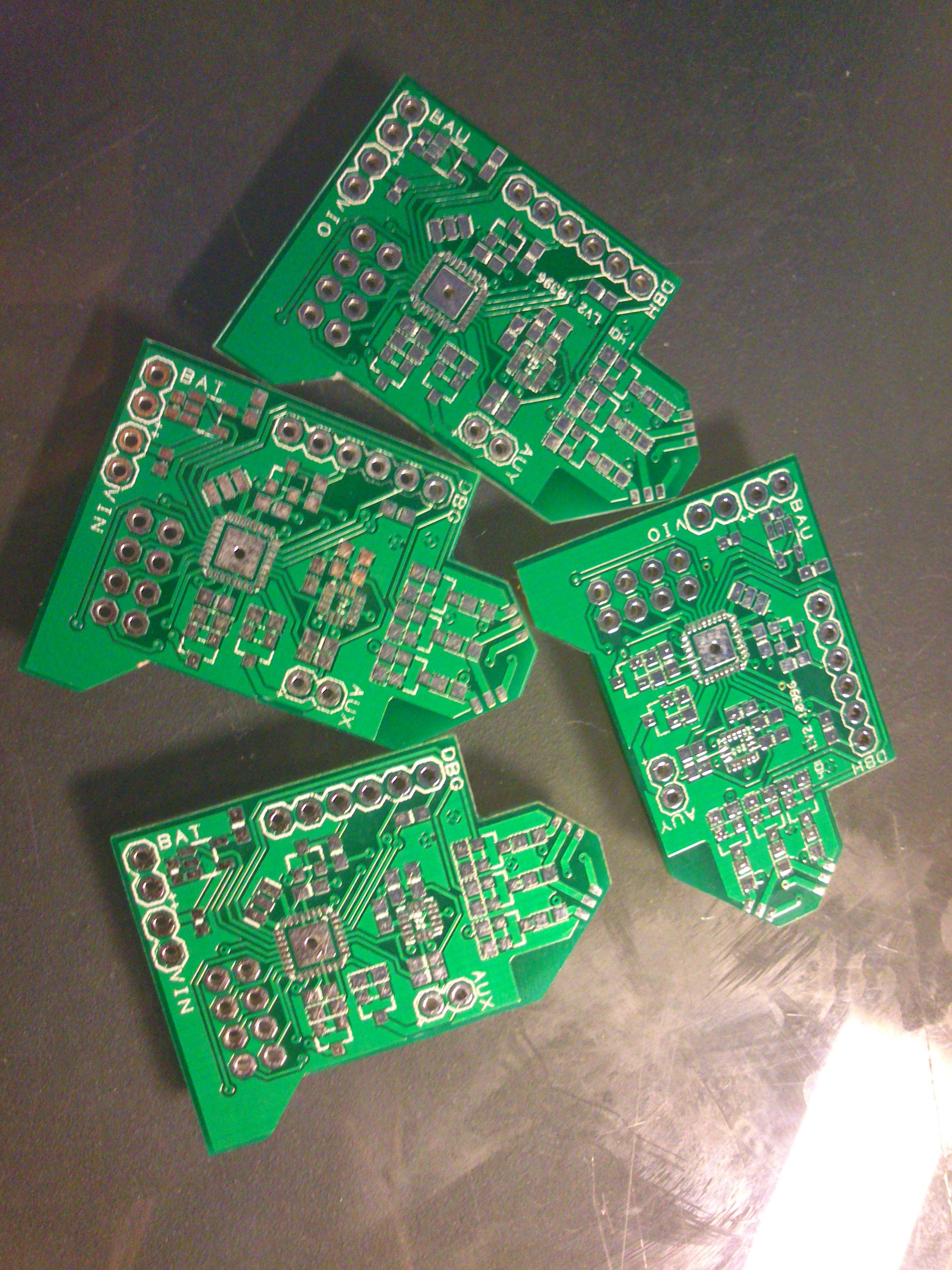
I started by looking into the properties of the Opentilt project. While being open and all the project was essentially just a carrier board for carrier boards. I happen to have a tray of atmega168's which I got at a place i was working. Now, it's the 8MHz version with only 16Kb memory so there's a challenge right there. I've previously made some Pro Mini clones with them (they're MLF packages) so i did my own board layout for them.
The system consist of at least two types of modules: the player (slave) and the main unit (master).
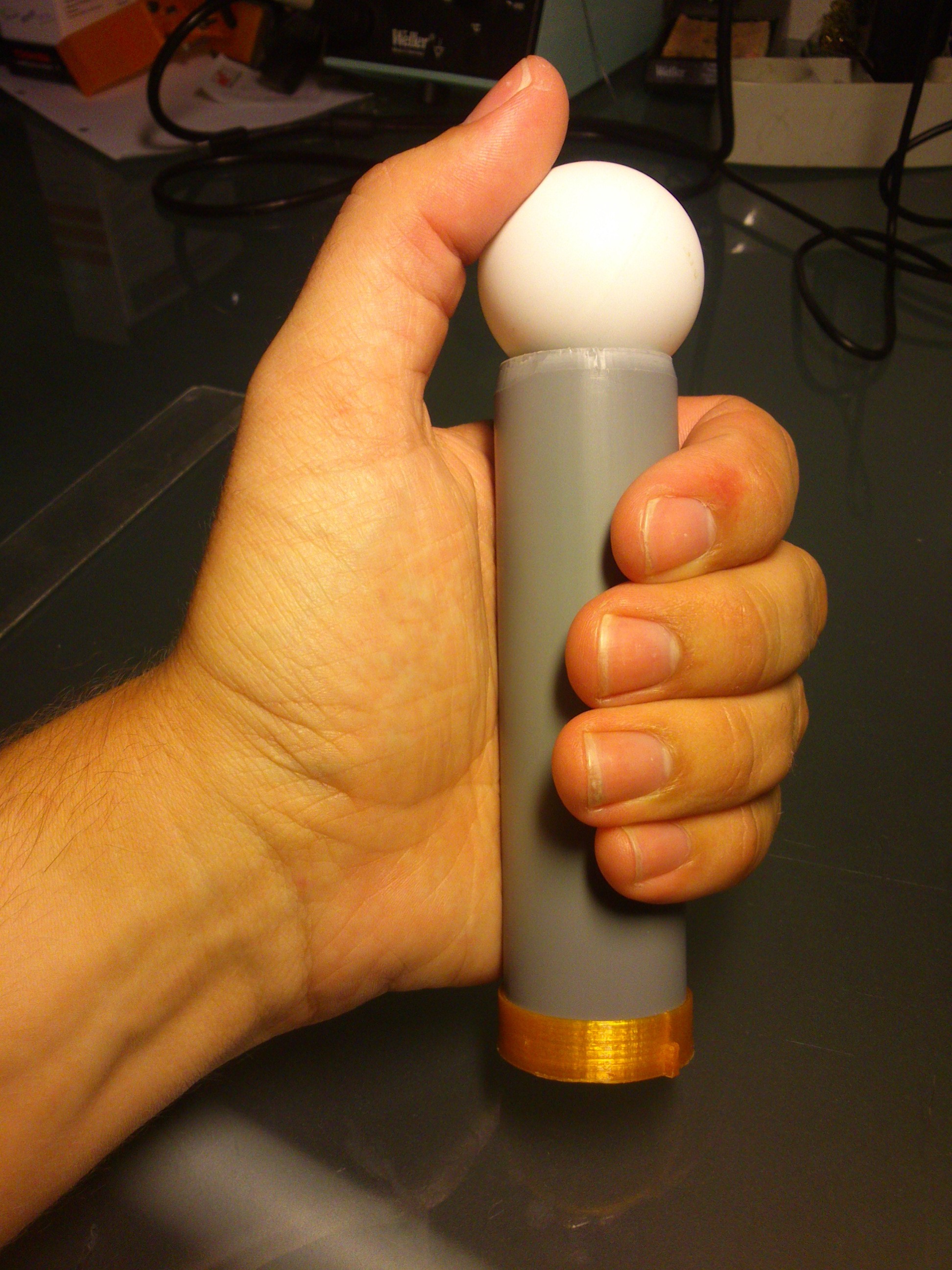
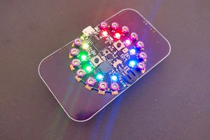
The player unit will need to be wireless, so I need some battery (which also means a charger and a regulator). A sensor (accelerometer) to measure the player movements, an indicator to tell the player the status of the game or the player itself (alive / dead/ barely hanging on to life). of course also a radio module and a microcontroller to tie it all together
The main unit will also need a radio to communicate with the player nodes. The rest of the main unit is at this stage undetermined. The unit could contain a music player if the game requires, tapping into the signal line doing basic beat detection to set speed. also it could play sound effects (start and finish sounds). The main unit could host some displays to tell the players the settings or status of the game etc.
The complete system is intended to be scalable and easy to reconfigure so it should be possible to play different kind of games on the same set of hardware
System Design (Player node)
The player node is the most important thing because the main node is essentially just a stationary player with the ability to send out instructions. the hardware is similar and yet a bit different. (The main node doesn't require accelerometer, for instance).
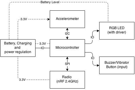
The block diagram shows the player node and their interactions along with power levels for each block. The microcontroller is in the middle of it all, providing logic and 'player funtionality'. It has the accelerometer, charger and radio as input and the LEDs busser and radio as output.
As for connectivity this is a great excercise for different bus topologies - I2C, SPI and the nRF protocol. Lots of failure points - lots of challenges!
First concept video and thoughts
The youtube video is done! I talk a little bit about the idea behind the project - to get people out from the living room and interact directly with each other.
A word on licensing
The OpenJoust is based somewhat on the Johann Sebastian Joust game and a bit more related to the OpenTilt game. Although it has similar functionality the fundamental idea of having a platform that can be used for multiple games differ from the two projects that are specifically designed for a single purpose (Johann Seabstian Joust don't even have special hardware, just Move controllers).
The Opentilt states that "The hardware design (based on closed source off-the-shelf components) and software source code are licensed under the GPL license.". As far as I can tell the only closed source entity in the Opentilt is the nRF radio - which is also used in this project.
The Johann Sebastian Joust game does not specify any licences and they do not offer any kind of code. I will assume that the whole project is closed source and only the information that I have been able to find through the demo video is used as inspiration for the OpenJoust platform.

 deʃhipu
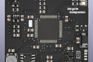
 Matias N.
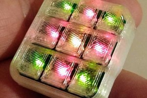
 Andrey Kalmatskiy
 Xasin
Xasin