Close
0%
0%

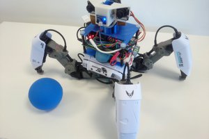
ZeroBot - Raspberry Pi Zero FPV Robot

Raspberry Pi Zero 3D Printed Video Streaming Robot

Similar projects worth following
ZeroBot is a Raspberry Pi Zero W based robot. It can be controlled using any computer or smartphone via a web browser. The integrated camera module makes for a low latency video stream. In addition the Raspberry Pi acts as a Wifi access point, so no router is required. The parts for the hull as well as the wheels can easily be printed on any regular 3D printer.

Some of the key features are:
- Compact CAD design with 3D printed components
- Analog control via a joystick (and multitouch)
- Simple battery solution using only a standard power bank
- Low latency streaming (~0.2s)
- Easy and cheap to build using widely available components

STL files on thingiverse: https://www.thingiverse.com/thing:2352440

View all 7 components

  • How to Get Started (Fall 2018)

    Max.K11/16/2018 at 22:01 5 comments

    For the Zerobot robot there are different instructions and files spread over Hackaday, Github and Thingiverse which may lead to some confusion. This project log is meant as a short guide on how to get started with building the robot. 

    Where do I start?

    1. Grab the STL-files from here: https://www.thingiverse.com/thing:2800717 and print them out following the instructions on Thingiverse
    2. Get the remaining parts: 
      - Raspberry Pi Zero W
      - 2x ICR18650 lithium cell 2600mAh
      - Raspberry camera module
      - Zero camera adapter cable
      - Mini DC dual motor controller
      - DC gear motors
      - ADS1115 ADC board
      - TP4056 USB charger
      - MT3608 boost converter
      - Raspberry CPU heatsink
      - Micro SD card (8GB or more)
      - 2x LED
      - BC337 transistor (or any other NPN) 
      - 11.5 x 6mm switch
      - 4x M3x10 screws and nuts
    3. Wire up the electronics according to this schematic: 
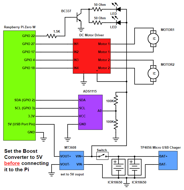
In case you are not familiar with this: The schematic is optimized for readability. You don't have to use this exact wiring (e.g. connection LEDs to ADS1115) as long as the electrical connections stay the same. For the wire gauges, use around 22 AWG wire for the signal connections and slightly thicker wire for the batteries and motors.
    4. The software comes preinstalled on an SD card image. Download it from here: https://drive.google.com/file/d/163jyooQXnsuQmMcEBInR_YCLP5lNt7ZE/view?usp=sharing, extract the files using 7-Zip and flash it to your 8GB micro SD card. Do not boot the Pi before entering your WiFi router name and password in the wpa_supplicant.conf file on the SD.
    5. After the SD card is inserted you can assemble the robot as seem on the pictures on the Hackaday project page. Make sure that all wires are properly isolated. Lithium batteries are very dangerous. If there is a short circuit between the batteries, they can catch fire. 
    6. Turn the robot on and wait for the Pi to connect to your WiFi. After that you can connect to it by accessing its IP followed by the port :3000 like this: 192.168.2.11:3000. If you don't know your Raspberry Pi's IP use a WiFi scanner like "Fing" on your smartphone to scan for devices.
    7. After that you are done! Have fun with your Zerobot! Below are some common questions/problems.

    The robot spins/ doesn't drive right

    The motors might be reversed. You can simply swap the two wires to fix this.

    I can't connect to the Zerobot in my browser

    The Raspberry Pi itself with the SD card image running on it is able to display the user interface in your browser. There is no additional hardware needed, so this can't be a hardware problem. Check if you are using the right IP and port and if you inserted the correct WiFi settings in the wpa_supplicant.conf file.

    I see the user interface but no camera stream

    Check if your camera is connected properly. Does it work on a regular Raspbian install?

    Zerobot and Zerobot Pro - What's the difference?

    The "pro" version is the second revision of the robot I built in 2017, which includes various hardware and software changes. Regardless of the hardware the "pro" software and SD-images are downwards compatible. I'd recommend building the latest version. New features like the voltage sensor and LEDs are of course optional.

    Can I install the software myself?

    If you don't want to use the provided SD image you can of course follow this guide to install the required software: https://hackaday.io/project/25092/instructions You should only do this if you are experienced with the Raspberry Pi. The most recent code is available on Github: https://github.com/CoretechR/ZeroBot

  • The new Zerobot Pro

    Max.K02/20/2018 at 22:02 28 comments

    All new features: More battery power, a charging port, battery voltage sensing, headlights, camera mode, safe shutdown, new UI

    The new software should work on all existing robots. 

    When I designed the ZeroBot last year, I wanted to have something that "just works". So after implementing the most basic features I put the parts on Thingiverse and wrote instructions here on Hackaday. Since then the robot has become quite popular on Thingiverse with 2800+ downloads and a few people already printed their own versions of it. Because I felt like there were some important features missing, I finally made a new version of the robot.

    The ZeroBot Pro has some useful, additional features:

    • Instead of a single battery with a power-bank circuit, the ZeroBot Pro is now powered by two 2600mAh batteries in parallel. Thanks to a cheap TP4056 Micro-USB charger the case does not have to be opened to recharge the batteries. 5V for the Pi and 6V (optional) for the motors are regulated by MT3608 boost converters.
    • Thanks to a ADS1115 ADC the Raspberry can measure the battery voltage and display it on the user interface
    • The entire user interface has been optimized for various screen sizes. There are now buttons for different functions:
      • A photo button for taking pictures in full resolution. This is not as easy as it appears. The stream has to be stopped to start the raspistill application and then restarts.
      • A toggle button to turn the LED headlights on and off. The LEDs are connected via a transistor to an IO pin. (I adopted this idea from franciscorps version of the ZeroBot: https://www.thingiverse.com/thing:2445551)
      • Finally there is a shutdown button that turns the Pi off safely after displaying a confirmation prompt. This should prevent the file system from corrupting
    • The 3D printed parts have been optimized as well to reduce warping and to fit the front panel more easily. 

    If you are interested in building the robot, you can head over here for the instructions: https://hackaday.io/project/25092/instructions 

    The 3D files are hosted on Thingiverse: https://www.thingiverse.com/thing:2800717

    Download the SD card image: https://drive.google.com/file/d/163jyooQXnsuQmMcEBInR_YCLP5lNt7ZE/view?usp=sharing

    After flashing the image to a 8GB SD card, open the file "wpa_supplicant.conf" with your PC and enter your WiFi settings.

  • Easy Setup using SD Image

    Max.K06/24/2017 at 13:07 17 comments

    After a few people ran into problems with the tutorial, I decided to create a less complicated solution. You can now download an SD card image for the robot, so there is no need for complicated installs and command line tinkering. The only thing left is getting the Pi into your network:

    1. Download the image file from here and unzip it to your PC: https://drive.google.com/uc?export=download&confirm=EUSf&id=0B4WbDsFout-NN1M1dzU0elR3NXc
    2. Flash the image to an 8GB or bigger micro SD card with the software of your choice (e.g. Etcher). Don't plug the SD into the Raspberry yet!
    3. In the boot partition of the SD, open the file wpa_supplicant.conf (e.g. using notepad). Change wifi ssid and password to your wifi name and password. The file will be automatically moved to its spot of the Pi's file system on boot. If you make a mistake, you just need to create the file again.
    4. After the Pi has booted up, find out its IP address using your routers interface or through an app like Fing. Connect to this address (e.g. 192.168.2.3) with any browser on your computer

    If you don't want the robot to be restricted to your home network, you can easily configure it to work as a wireless access point. This is described in the tutorial.

    EDIT 29.7. Even easier setup - the stream ip is selected automatically now

  • Introduction

    Max.K05/29/2017 at 20:53 1 comment

    The goal for this project was to build a small robot which could be controlled wirelessly with video feed being sent back to the user. Most of my previous projects involved Arduinos but while they are quite capable and easy to program, there are a lot of limitations with simple microcontrollers when it comes to processing power. Especially when a camera is involved, there is now way around a Raspberry Pi. The Raspberry Pi Zero W is the ideal hardware for a project like this: It is cheap, small, has built in Wifi and enough processing power and I/O ports.

    Because I had barely ever worked with a Raspberry, I first had to find out how to program it and what software/language to use. Fortunately the Raspberry can be set up to work without ever needing to plug in a keyboard or Monitor and instead using a VNC connection to a remote computer. For this, the files on the boot partition of the SD card need to be modified to allow SSH access and to connect to a Wifi network without further configuration.

    The next step was to get a local website running. This was surprisingly easy using Apache, which creates and hosts a sample page after installing it.

    To control the robot, data would have to be sent back from the user to the Raspberry. After some failed attempts with Python I decided to use Node.js, which features a socket.io library. With the library it is rather easy to create a web socket, where data can be sent to and from the Pi. In this case it would be two values for speed and direction going to the Raspberry and some basic telemetry being sent back to the user to monitor e.g. the CPU temperature.

    For the user interface I wanted to have a screen with just the camera image in the center and an analog control stick at the side of it. While searching the web I found this great javascript example by Seb Lee-Delisle: http://seb.ly/2011/04/multi-touch-game-controller-in-javascripthtml5-for-ipad/ which even works for multitouch devices. I modified it to work with a mouse as well and integrated the socket communication.

    I first thought about using an Arduino for communicating with the motor controller, but this would have ruined the simplicity of the project. In fact, there is a nice Node.js library for accessing the I/O pins: https://www.npmjs.com/package/pigpio. I soldered four pins to the PWM motor controller by using the library, the motors would already turn from the javascript input.

    After I finally got a camera adapter cable for the Pi Zero W, I started working on the stream. I used this tutorial to get the mjpg streamer running: https://www.youtube.com/watch?v=ix0ishA585o. The latency is surprisingly low at just 0.2-0.3s with a resolution of 640x480 pixels. The stream was then included in the existing HTML page.

    With most of the software work done, I decided to make a quick prototype using an Asuro robot. This is a ancient robot kit from a time before the Arduino existed. I hooked up the motors to the controller and secured the rest of the parts with painters tape on the robot's chassis:

    After the successful prototype I arranged the components in Fusion 360 to find a nice shape for the design. From my previous project (http://coretechrobotics.blogspot.com/2015/12/attiny-canbot.html) I knew that I would use a half-shell design again and make 3D printed parts.

    The parts were printed in regular PLA on my Prusa i3 Hephestos. The wheels are designed to have tires made with flexible filament (in my case Ninjaflex) for better grip. For printing the shells, support materia is necessary. Simplify3D worked well with this and made the supports easy to remove.

    After printing the parts and doing some minor reworking, I assembled the robot. Most components are glued inside the housing. This may no be professional approach, but I wanted to avoid screws and tight tolerances. Only the two shells are connected with four hex socket screws. The corresponding nuts are glued in on the opposing shell. This makes it easily to access the internals of the robot.

    For...

    Read more »

View all 4 project logs

  • 1
    Installing The Latest Raspbian Image

    DISCLAIMER: This is not a comprehensive step-by-step tutorial. Some previous experience with electronics / Raspberry Pi is required. I am not responsible for any damage done to your hardware.

    I am also providing an easier alternative to this setup process using a SD card image: https://hackaday.io/project/25092/log/62102-easy-setup-using-sd-image

    https://www.raspberrypi.org/documentation/installation/installing-images/

    This tutorial is based on Raspbian Jessie 4/2017

    Personally I used the Win32DiskImage for Windows to write the image to the SD card. You can also use this program for backing up the SD to a .img file.

    IMPORTANT: Do not boot the Raspberry Pi yet!

  • 2
    Headless Setup

    Access the Raspberry via your Wifi network with VNC:

    Put an empty file named "SSH" in the boot partiton on the SD.

    Create a new file "wpa_supplicant.conf" with the following content and move it to the boot partition as well:

    ctrl_interface=DIR=/var/run/wpa_supplicant GROUP=netdev
    update_config=1
    network={
        ssid="wifi name"
        psk="wifi password"
    }

    Only during the first boot this file is automatically moved to its place in the Raspberry's file system.

    After booting, you have to find the Raspberry's IP address using the routers menu or a wifi scanner app.

    Use Putty or a similar program to connect to this address with your PC.

    After logging in with the default details you can run

    sudo raspi-config

    In the interfacing options enable Camera and VNC

    In the advanced options expant the file system and set the resolution to something like 1280x720p.

    Now you can connect to the Raspberry's GUI via a VNC viewer: https://www.realvnc.com/download/viewer/

    Use the same IP and login as for Putty and you should be good to go.

  • 3
    Installing the required software (update 2018)
    sudo apt-get update
    sudo apt-get upgrade
    sudo apt-get install apache2 node.js npm
    git clone https://github.com/CoretechR/ZeroBot Desktop/touchUI
    cd Desktop/touchUI
    sudo npm install express
    sudo npm install socket.io
    sudo npm install pi-gpio
    sudo npm install pigpio
    

    Run the app.js script using:

    cd Desktop/touchUI
    sudo node app.js

    You can make the node.js script start on boot by adding these lines to /etc/rc.local before "exit 0":

    cd /home/pi/Desktop/touchUI
    sudo node app.js&
    cd

    The HTML file can easily be edited while the node script is running, because it is sent out when a host (re)connects.

View all 7 instructions

Enjoy this project?

Share

Discussions

Dan DWRobotics wrote 07/29/2017 at 21:26 point

Such a well thought out and well designed project. It all seems to work so perfectly, combining multiple skills to make it work.

  Are you sure? yes | no

Robert Kränzlein wrote 07/18/2017 at 12:00 point

Is there any config file? Forward and backwards works fine, but my steering works the wrong way.

  Are you sure? yes | no

Max.K wrote 07/18/2017 at 15:21 point

You can either change the wiring or look for the files touchUI or app.js in the folder TouchUI on the desktop. Its probably the easiest thing to just swap the cables for the left and right motor.

  Are you sure? yes | no

Robert Kränzlein wrote 07/18/2017 at 15:47 point

I found the touch.html-File and added

x = 0 - x; 

to the function tankDrive(x, y). Now the bot works fine!

  Are you sure? yes | no

5haun wrote 07/08/2017 at 04:48 point

Works very well-- Even over the internet. Impressed by how responsive the websocket/mjpg combo is and how intuitive the browser based controls are. I used two batteries, added a charging port, and it still fits just fine. Thanks for the guide!

  Are you sure? yes | no

Max.K wrote 07/08/2017 at 07:38 point

That's great to hear! If you want you could upload a picture of your robot to Thingiverse: 

https://www.thingiverse.com/thing:2352440/add_instance

  Are you sure? yes | no

MP wrote 07/01/2017 at 00:05 point

Hey! I finally made it! Works pretty well and the video stream is pretty responsive.

One thing though... it's quite difficult to control, especially because it turns so easily... One slight movement to the right/left, and it starts spinning. Is there any way to adjust the sensitivity?

  Are you sure? yes | no

Max.K wrote 07/02/2017 at 07:23 point

Well done so far! The motors are not really made for slow movement. I tried to adjust the dead-zone so that the robot starts driving immediately instead of just beeping the motors. You can reverse this by removing these lines of code from Touch.html:

if(leftMot > 0) leftMot += 90;
if(leftMot < 0) leftMot -= 90;
if(rightMot > 0) rightMot += 90;
if(rightMot < 0) rightMot -= 90;

A charging port would be nice and will definitely be included if I'm going to make a second version. Right now you can easily modify the original CAD files (link is on this page) to include any charging port you need.

  Are you sure? yes | no

MP wrote 07/28/2017 at 18:05 point

Thanks. I tried that, but removing the dead zone does not completely solve the quick spin issue. I have to figure out a way to indicate that if there is not enough forward speed, turning has to be slower than the indicated.

By the way. I tried adding a microsub port on the back, but soldering it was a pain as it kept desoldering itself. I ended up creating a dock, just like a roomba. It is much easier to charge it this way, and it is possible to leave it powered on and ready to move.

  Are you sure? yes | no

MP wrote 06/30/2017 at 12:25 point

By the way, it would be convenient to have an opening in the back for a female microusb port, in order to charge the robot without having to open the cover.

  Are you sure? yes | no

corduroymango wrote 06/24/2017 at 19:55 point

Got it all up and running, can't get it to reverse? Any ideas?

  Are you sure? yes | no

tom.sfo wrote 06/26/2017 at 13:37 point

I'm planning to use code and all instruction of this great project to hack a RC car featuring two motor driving 2 wheels each from the same side. Of course it'd be better if it may go reverse. I'm interested in answer to your request !

Have a nice day

  Are you sure? yes | no

Max.K wrote 07/02/2017 at 07:08 point

Sorry for the late response. The Hackaday.io feed seems to show me anything but comments on my projects. Have you tried measuring the voltages on the GPIO pins (with a multimeter) when driving forward/backward? It should read 0-3.3 V.

  Are you sure? yes | no

juandelacosta wrote 06/23/2017 at 14:31 point

where did people get the ninjaflex printed tires made at?

  Are you sure? yes | no

tom.sfo wrote 06/26/2017 at 13:38 point

Try sculpteo for flexible filament, i.materialise, or even 3dhubs.com for lower price

  Are you sure? yes | no

Gangwisch wrote 06/13/2017 at 07:48 point

Sorry now I see I have n Error:

pi@raspberrypi:~/Desktop/touchUI $ sudo node app.js
2017-06-13 09:47:26 initInitialise: Can't lock /var/run/pigpio.pid
/home/pi/Desktop/touchUI/node_modules/pigpio/pigpio.js:11
    pigpio.gpioInitialise();
           ^
Error: pigpio error -1 in gpioInitialise
    at initializePigpio (/home/pi/Desktop/touchUI/node_modules/pigpio/pigpio.js:11:12)
    at new Gpio (/home/pi/Desktop/touchUI/node_modules/pigpio/pigpio.js:25:3)
    at Object. (/home/pi/Desktop/touchUI/app.js:9:8)
    at Module._compile (module.js:569:30)
    at Object.Module._extensions..js (module.js:580:10)
    at Module.load (module.js:503:32)
    at tryModuleLoad (module.js:466:12)
    at Function.Module._load (module.js:458:3)
    at Function.Module.runMain (module.js:605:10)
    at startup (bootstrap_node.js:158:16)

  Are you sure? yes | no

Max.K wrote 06/13/2017 at 19:15 point

It is possible that the autostart script is already running while you are trying to start it manually. Did you remove these lines for testing from rc.local?

cd /home/pi/Desktop/touchUI

sudo node app.js&
cd

Try to remove these lines, the cd into the touchUI folder and run app.js

Anyway I'm not much of an expert on Raspberry Pi or Linux so I don't really know if I can help you with this.

  Are you sure? yes | no

Gangwisch wrote 06/13/2017 at 19:44 point

when I install the pacetes it looks like so:

pi@raspberrypi:~/Desktop/touchUI $ sudo npm install express
npm WARN saveError ENOENT: no such file or directory, open '/home/pi/package.json'
npm WARN enoent ENOENT: no such file or directory, open '/home/pi/package.json'
npm WARN pi No description
npm WARN pi No repository field.
npm WARN pi No README data
npm WARN pi No license field.
+ express@4.15.3
added 42 packages in 47.102s
pi@raspberrypi:~/Desktop/touchUI $ sudo npm install socket.io
npm WARN deprecated isarray@2.0.1: Just use Array.isArray directly
> uws@0.14.5 install /home/pi/node_modules/uws
> node-gyp rebuild > build_log.txt 2>&1 || exit 0
npm WARN saveError ENOENT: no such file or directory, open '/home/pi/package.json'
npm WARN enoent ENOENT: no such file or directory, open '/home/pi/package.json'
npm WARN pi No description
npm WARN pi No repository field.
npm WARN pi No README data
npm WARN pi No license field.
+ socket.io@2.0.3
added 36 packages in 361.082s
pi@raspberrypi:~/Desktop/touchUI $ sudo npm install pi-gpio
npm WARN saveError ENOENT: no such file or directory, open '/home/pi/package.json'
npm WARN enoent ENOENT: no such file or directory, open '/home/pi/package.json'
npm WARN pi No description
npm WARN pi No repository field.
npm WARN pi No README data
npm WARN pi No license field.
+ pi-gpio@0.0.8
added 1 package in 24.732s
pi@raspberrypi:~/Desktop/touchUI $ sudo npm install websocket
> websocket@1.0.24 install /home/pi/node_modules/websocket
> (node-gyp rebuild 2> builderror.log) || (exit 0)
make: Entering directory '/home/pi/node_modules/websocket/build'
  CXX(target) Release/obj.target/bufferutil/src/bufferutil.o
  SOLINK_MODULE(target) Release/obj.target/bufferutil.node
  COPY Release/bufferutil.node
  CXX(target) Release/obj.target/validation/src/validation.o
  SOLINK_MODULE(target) Release/obj.target/validation.node
  COPY Release/validation.node
make: Leaving directory '/home/pi/node_modules/websocket/build'
npm WARN saveError ENOENT: no such file or directory, open '/home/pi/package.json'
npm WARN enoent ENOENT: no such file or directory, open '/home/pi/package.json'
npm WARN pi No description
npm WARN pi No repository field.
npm WARN pi No README data
npm WARN pi No license field.
+ websocket@1.0.24
added 4 packages in 84.744s
pi@raspberrypi:~/Desktop/touchUI $ sudo npm install pigpio
> pigpio@0.6.0 install /home/pi/node_modules/pigpio
> node-gyp rebuild
gyp WARN EACCES user "root" does not have permission to access the dev dir "/root/.node-gyp/8.1.0"
gyp WARN EACCES attempting to reinstall using temporary dev dir "/home/pi/node_modules/pigpio/.node-gyp"
make: Entering directory '/home/pi/node_modules/pigpio/build'
  CXX(target) Release/obj.target/pigpio/src/pigpio.o
  SOLINK_MODULE(target) Release/obj.target/pigpio.node
  COPY Release/pigpio.node
make: Leaving directory '/home/pi/node_modules/pigpio/build'
npm WARN saveError ENOENT: no such file or directory, open '/home/pi/package.json'
npm WARN enoent ENOENT: no such file or directory, open '/home/pi/package.json'
npm WARN pi No description
npm WARN pi No repository field.
npm WARN pi No README data
npm WARN pi No license field.
+ pigpio@0.6.0
updated 1 package in 70.828s

And no I have only a black background and the camera live Picture

  Are you sure? yes | no

Max.K wrote 06/13/2017 at 20:08 point

I'm sorry but I can't do more than google your error messages. I don't know what the problem is. Maybe you have to start from a fresh install.

  Are you sure? yes | no

MP wrote 06/28/2017 at 23:29 point

I get exactly the same error message (Raspberry Pi B, debian wheezy). I should try it on a fresh install.

  Are you sure? yes | no

Gangwisch wrote 06/10/2017 at 09:47 point

Thank you for your answer @Ole Madsen.

now when I give my "ip:3000" I see the  live picture from the camera.

I don´t see in the left corner the text an when I click with the mouse I don´t see this rings

  Are you sure? yes | no

Max.K wrote 06/12/2017 at 18:51 point

Sorry for replying so late. 

Have you solved the problem yet? 

You have to connect to the port that contains the html/javascript (probably 9000). If you connect to the camera (3000), you will only see the stream.

  Are you sure? yes | no

Gangwisch wrote 06/12/2017 at 19:42 point

hey, no i dont sloved my Problem...

With witch port i shoud use too drive the robot.

The port 9000 ist the prort from the camera... i got the site to set the camera ...

With witch port can i drive the robot.

Thank you for your help

The projekt is verry good i Love it

  Are you sure? yes | no

Max.K wrote 06/13/2017 at 05:46 point

I was wrong with the ports at first: According to my tutorial and file, the port for controls and camera is 3000 (it is defined in app.js). If you see the camera and a black background, that means you already have a running node.js script. Maybe you are missing a library. Are you starting the node.js script from the command line or is it already set to autostart? In the command line are there any warning when starting the script?

  Are you sure? yes | no

Gangwisch wrote 06/07/2017 at 20:14 point

I have following problem:

Can anyone help me, where the Problem are?

pi@raspberrypi:~/Desktop/touchUI $ sudo npm install socket
npm WARN engine socket@0.0.1: wanted: {"node":">= 0.6.0 < 0.7.0"} (current: {"node":"0.10.29","npm":"1.4.21"})
/
> microtime@0.2.0 install /home/pi/Desktop/touchUI/node_modules/socket/node_modules/microtime
> node-waf configure build
sh: 1: node-waf: not found
npm WARN This failure might be due to the use of legacy binary "node"
npm WARN For further explanations, please read
/usr/share/doc/nodejs/README.Debian
npm ERR! microtime@0.2.0 install: `node-waf configure build`
npm ERR! Exit status 127
npm ERR!
npm ERR! Failed at the microtime@0.2.0 install script.
npm ERR! This is most likely a problem with the microtime package,
npm ERR! not with npm itself.
npm ERR! Tell the author that this fails on your system:
npm ERR!     node-waf configure build
npm ERR! You can get their info via:
npm ERR!     npm owner ls microtime
npm ERR! There is likely additional logging output above.
npm ERR! System Linux 4.9.24+
npm ERR! command "/usr/bin/nodejs" "/usr/bin/npm" "install" "socket"
npm ERR! cwd /home/pi/Desktop/touchUI
npm ERR! node -v v0.10.29
npm ERR! npm -v 1.4.21
npm ERR! code ELIFECYCLE
npm ERR!
npm ERR! Additional logging details can be found in:
npm ERR!     /home/pi/Desktop/touchUI/npm-debug.log
npm ERR! not ok code 0

  Are you sure? yes | no

Ole Madsen wrote 06/09/2017 at 11:37 point

hi, I think it is a very cool project! But I also got the same problem. 

But I did found out it was problably an type error in the guide and an error with node.js version. So here is an updatede guide that should work :-)

cd ~

wget https://nodejs.org/dist/latest/node-v8.1.0-linux-armv6l.tar.gz
cd /usr/local
sudo tar xzvf ~/node-v8.1.0-linux-armv6l.tar.gz --strip=1
cd ~
sudo apt-get install apache2 npm git
git clone https://github.com/CoretechR/ZeroBot Desktop/touchUI
cd Desktop/touchUI
sudo npm install express
sudo npm install socket.io
sudo npm install pi-gpio
sudo npm install websocket


+install this way https://github.com/fivdi/pigpio#installation

the run


sudo npm install pigpio

If you run off you own router, please change the touch.html. http://10.0.0.1:9000 to your ip:9000. ex. http://192.168.1.22:9000

  Are you sure? yes | no

Max.K wrote 06/13/2017 at 05:52 point

Thanks a lot for your solution. I will try to update the instructions.

  Are you sure? yes | no

BokTech wrote 06/06/2017 at 14:55 point

Will you add more usage for the video robot?

  Are you sure? yes | no

Max.K wrote 06/06/2017 at 16:31 point

Yes, but probably at a later time. OpenCV would be a nice addition.

  Are you sure? yes | no

Wudagem wrote 06/05/2017 at 16:10 point

Would you consider making the Fusion 360 Models available, so they can be modified easily?

  Are you sure? yes | no

Max.K wrote 06/13/2017 at 07:33 point

No problem, a link to the Fusion 360 model is now on the project page.

  Are you sure? yes | no

guiducci.alessandro wrote 06/05/2017 at 14:13 point

Hi Max, can i supply 5V to both raspberry and DC driver

  Are you sure? yes | no

Max.K wrote 06/05/2017 at 15:51 point

The 5V should not be coming from the same source. The noise from the motors can potentially harm the Raspberry. Try to use two voltage sources, but both devices can handle 5V.

  Are you sure? yes | no

juandelacosta wrote 08/31/2017 at 11:04 point

how do we use the single 5vlt source for both some kind of caps or something on the motors?

  Are you sure? yes | no

juandelacosta wrote 06/03/2017 at 06:54 point
2600mAh Power Bank

 what brand?

  Are you sure? yes | no

Craig Hissett wrote 06/01/2017 at 19:15 point

This is bloody marvellous matey!

The design is fantastic, and the use of common parts marks this a fantastic project.

I need to get this printed somewhere!

  Are you sure? yes | no

andy.meggs wrote 06/01/2017 at 14:46 point

Can this be made to be controlled from anywhere? Connect to router with port-

forwarding?

  Are you sure? yes | no

Max.K wrote 06/01/2017 at 15:16 point

Yes, connecting it to a router is much easier than the access point mode. Port forwarding should not be a problem from there.

  Are you sure? yes | no

juandelacosta wrote 06/01/2017 at 08:25 point

Raspberry Camera Module. is this version 2 or 1?

  Are you sure? yes | no

Max.K wrote 06/01/2017 at 10:22 point

It is the first version with 5MP.

  Are you sure? yes | no

Similar Projects

Does this project spark your interest?

Become a member to follow this project and never miss any updates