 Timo Birnschein
Part List:
- 8 x LM12UU
- 4 x LM8UU
- 2 x 12mm x 260mm hardened linear rod
- 2 x 12mm x 240mm hardened linear rod
- 2 x 8mm x 110mm hardened linear rod
- 3 x 8mm to 5mm aluminium coupler
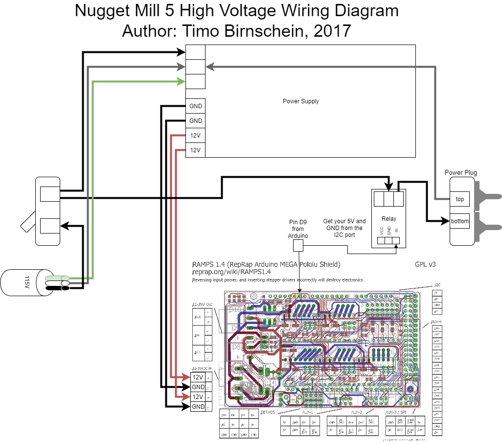
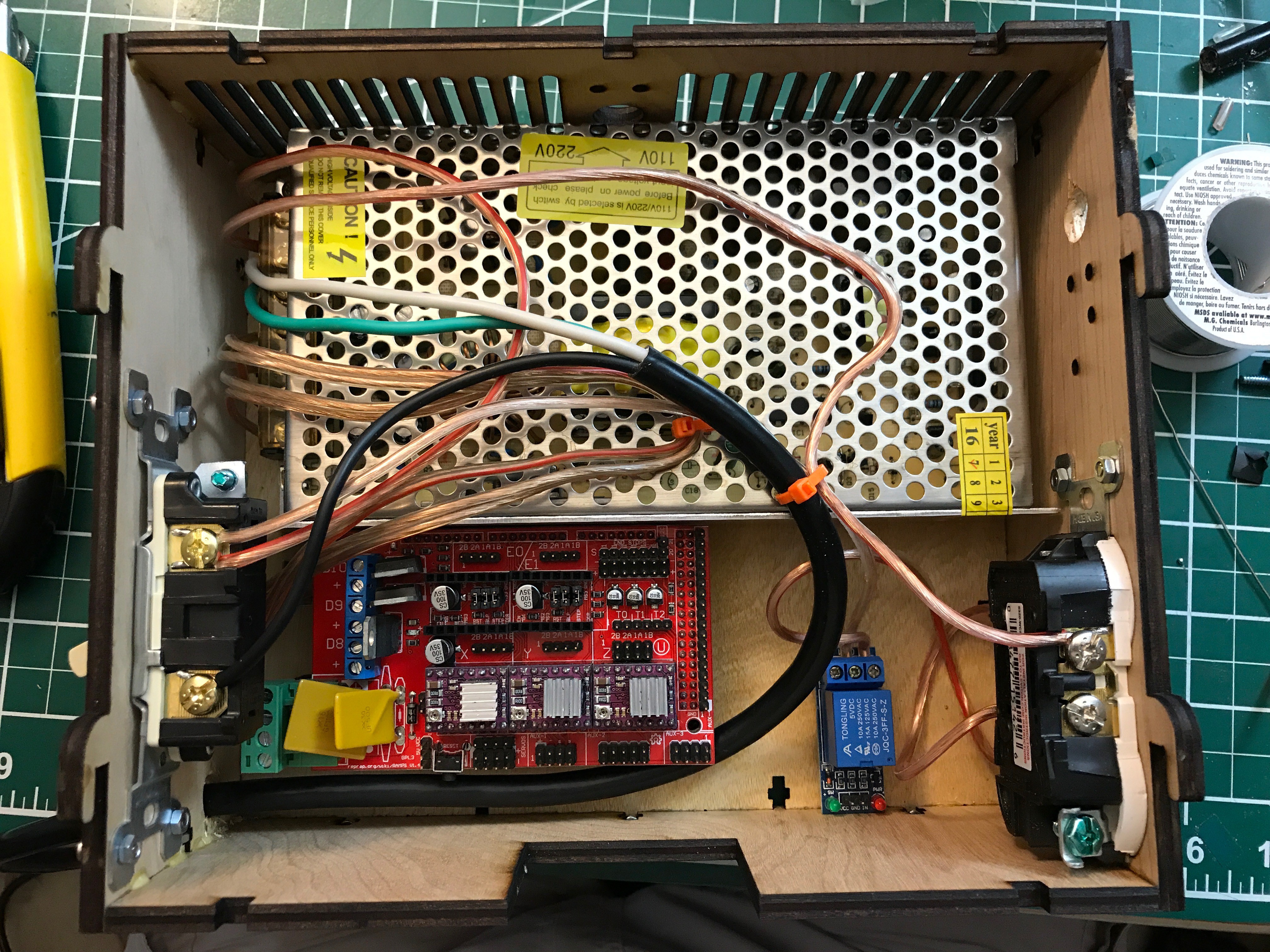
- 1 x DC 12V 10A 120W power supply
- 1 x Ramps 1.4 kit with stepper motors and Adruino Mega Controller and end stops
- 1 x 8mm x 260mm T8x8 trapezoidal threaded rod with brass nut
- 1 x 8mm x 240mm T8x8 trapezoidal threaded rod with brass nut
- 1 x 8mm x 80mm T8x2 trapezoidal threaded rod with brass nut
- 1 x 5V relay module for automatic spindle control
- 1 x sheet of 5mm plywood from home depot and a circular saw to cut it to 200mm x 300mm sheets (I suggest going with something more expensive than I did)
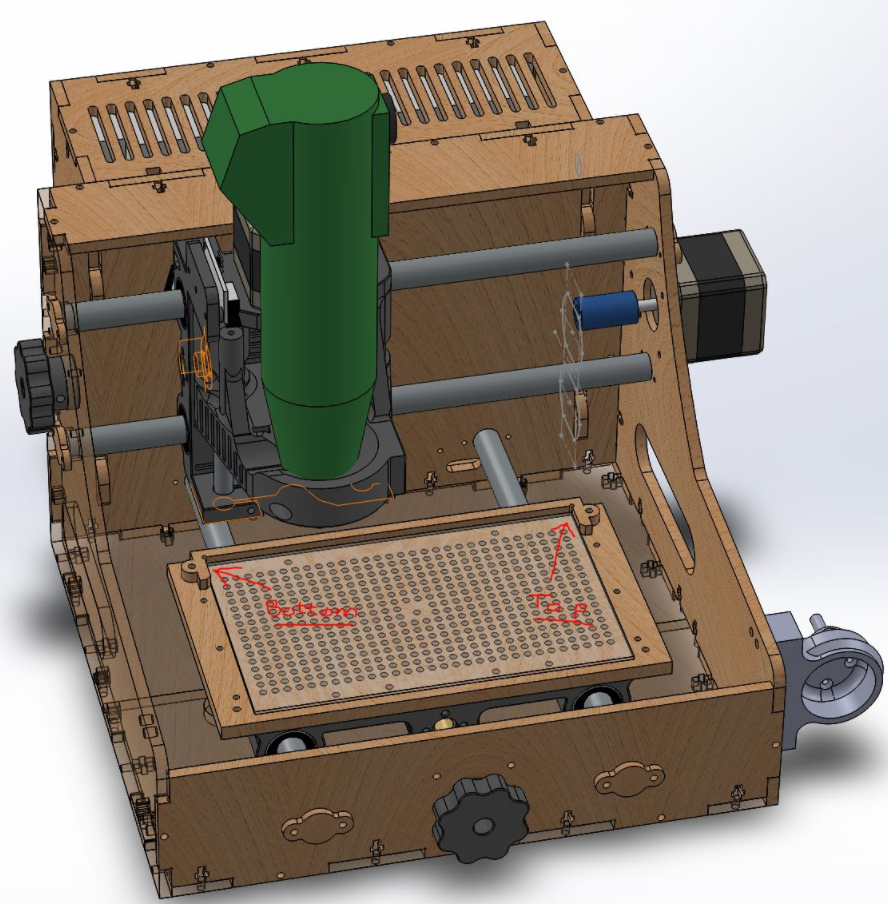
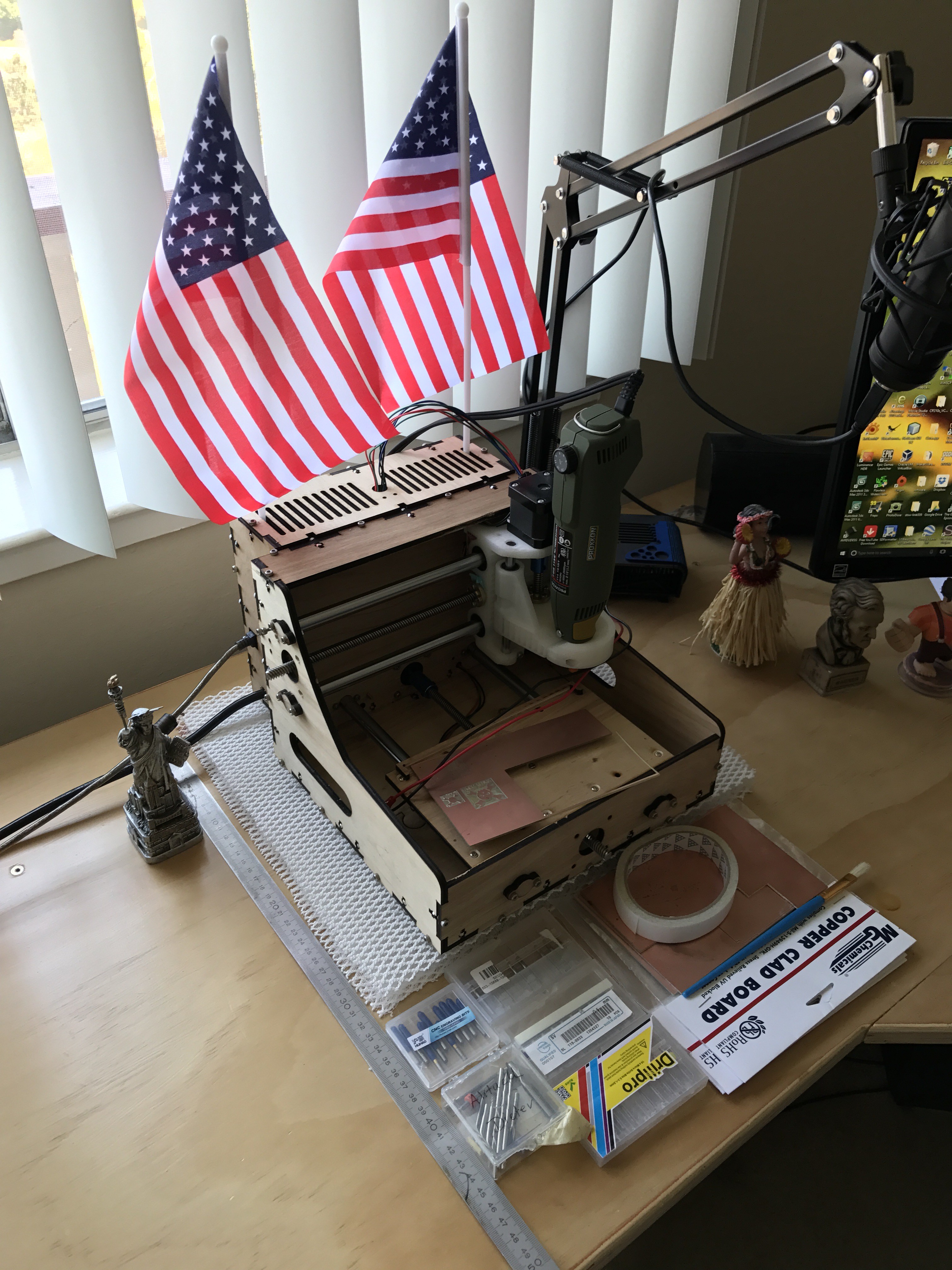
- 1 x Proxxon FBS 115/E because the original dremel is not precise enough!
- 1 x Proxxon 28940 steel collet set for high precision milling
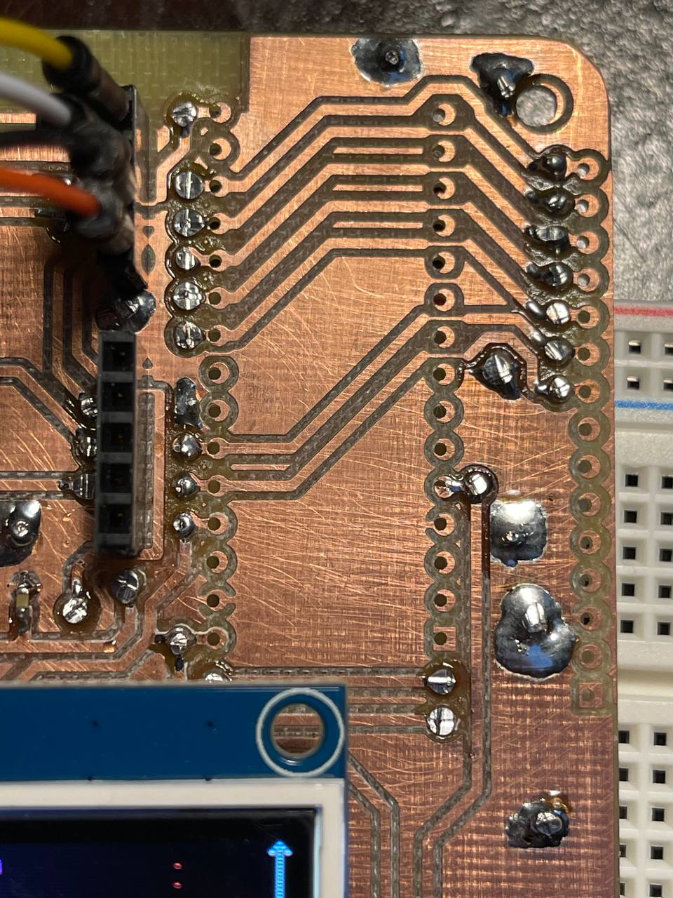
- 1 x 30 degree 0.2mm PCB engraving bits with titanium coating
- 1 x 1mm PCB milling bits with carbide coating
- 1 x Varying drill bits between 0.3mm to 1.2mm
- 1 x Wall mount toggle switch as 15A on/off switch
- 1 x Wall mount wall power plug for spindle
It would be good to have access to a laser cutter to make this. Otherwise just order the parts including material from your local laser cutting shop.
Print Instructions:
I use KisSlicer for printing my parts! I use it because it offers a VERY valuable function which calculates insets for holes. Properly calibrated, this gives me exactly 12mm when I design a 12mm hole! For all parts, this means that I can pressfit my linear bushings! Please keep that in mind before you kick of your 10h prints!


 Sam Griffen
 mosaicmerc
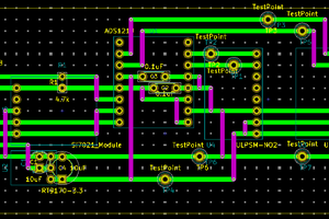
 Mike Teachman
 PCB designer
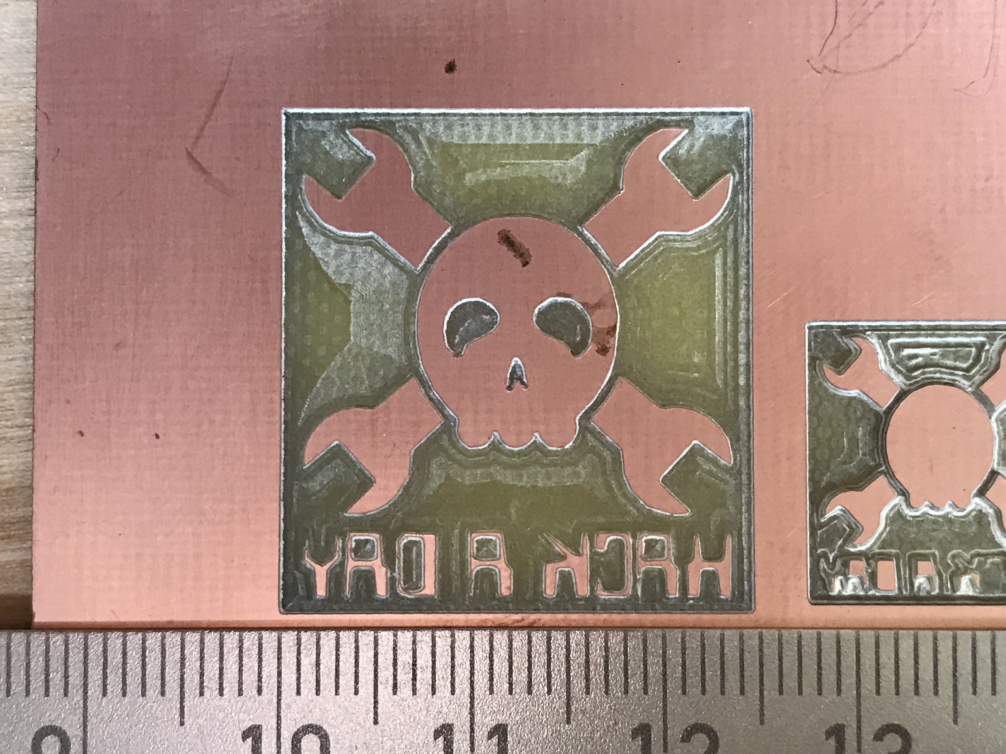
Hi Timo. Thanks for the skull/follow for #Minamil! It won't do 100x160mm, but I wonder -- since you've had this machine for a few years by now -- how much of what you do with this could be done in 55mm+ x 55mm+, or maybe 70mm x 70mm?