 Matt Barr
Design & Cost
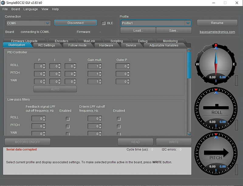
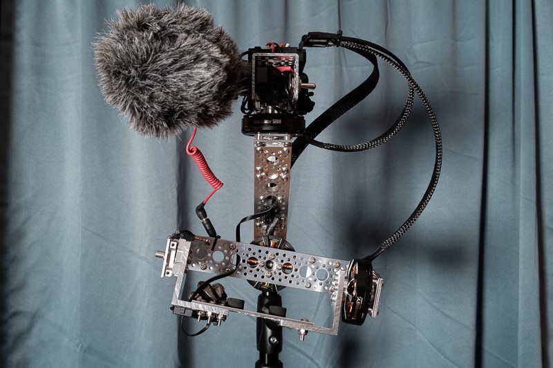
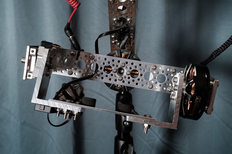
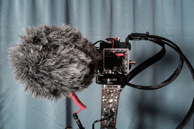
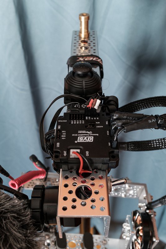
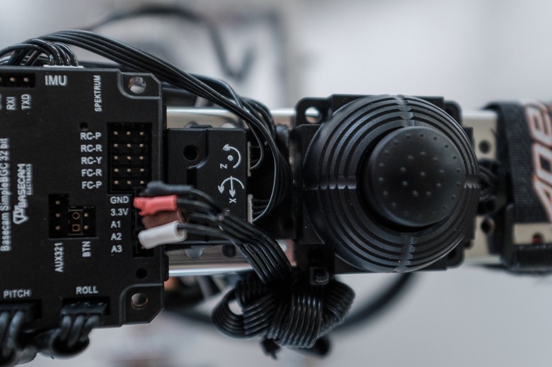
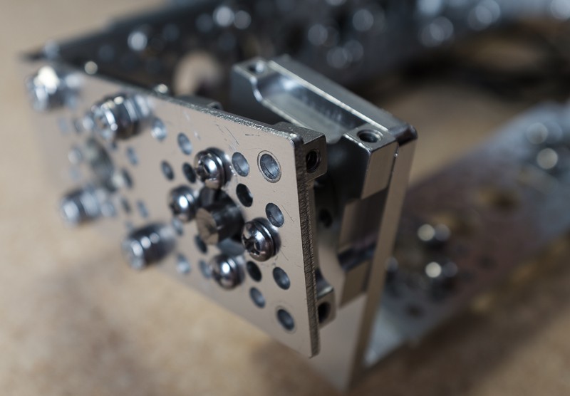
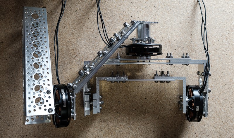
The goal with this project is to build a high-performance gimbal for mirrorless and DSLRs. The design for this gimbal has a similar form factor to the DJI RONIN, except smaller and made of aluminum. The plan is to have 3-axis rotation, with a smallish form factor, with all electrical components on the grip for under $300.
Weight: 2.8 Lb.
Total Width: 8.5"
Total Depth: 12"
Total Height: 10.25"
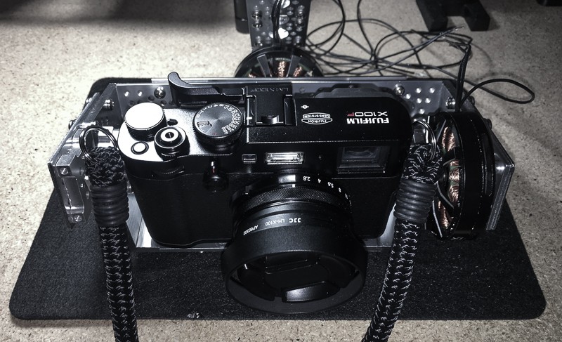
Max Camera Width: 5.5" (As Configured)
Max Camera Height: 6.25" (As Configured)
My Build Cost: $244.84 (Minus Shorted Board)
Build Cost From Scratch: Probably around $300.


 JanThar
 Quinn
Quinn
 Daren Schwenke
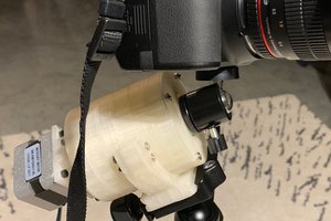
 Chris
Chris
I did not know such a thing existed back in 2017. Everything I saw commercially was prohibitively expensive.