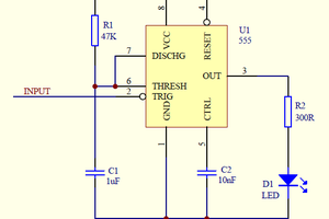
This security alarm works by NE555 timer and logic gates. When the ON-OFF selector is open the input pins of the IC2 timer takes the low level from the Q11 collector. The security alarm does not work because the IC2 output is high, so the Q12 collector keeps down the Q3-Q4 transistors.
When you close the ON-OFF selector the IC2 output turns down with a time delay given by the C5 capacitor. Once the security alarm starts working the red led turns on. So, if a door sensor changes condition, an output (3 or 11) of the CD4030 logic gate switches on for a bit.
The IC1 timer switches on and turns down the Q7 transistor, so the IC3 timer starts counting. The IC3 output activates the security alarm sound, which stops due to the IC4 timer.
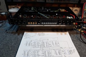
The circuit you see in the video works with a small time delay, because I used small C3-C4 capacitors. By using the values indicated in the circuit schematic the security alarm should work with a time delay of about 10-15 seconds.
 Andrea De Napoli


 Keri Szafir
 Ted Yapo