Close
0%
0%

Bloodhound: Autonomous Radiolocation Drone

Speeding up Search & Rescue by locating the position of emergency radio beacons using an autonomous drone.

Similar projects worth following
Bloodhound is a project to create a drone/UAV for autonomously locating the position of a radio beacon, using passive Radio Direction Finding (RDF) techniques. Built around the open-source Ardupilot autopilot system and cheap Software Defined Radio (SDR) technology, the project aims to produce an affordable (built on an engineering student budget!) radiolocation system to speed up the process of locating emergency beacons, track wildlife beacons, locate amateur rockets, or find the source of errant radio signals.

All original hardware associated with this project is licensed under CERN OHL v1.2.

All original firmware/software associated with this project is licensed under LGPLv3.


The Problem

Emergency Radio Beacons
Radio beacons are used in many sectors to track or locate people, animals and other important assets. They are also widely used in Search and Rescue (SAR) situations, and are present on most aircraft, marine vessels and also used by people venturing into remote areas, where they are known as Emergency Position Indicator Radio Beacons (EPIRBs). Whilst some emergency beacons are capable of sending out their exact GPS location, the majority of them can only be systematically located to an area of several square kilometres, requiring a traditional SAR grid search at this location, either on foot or from manned aircraft.

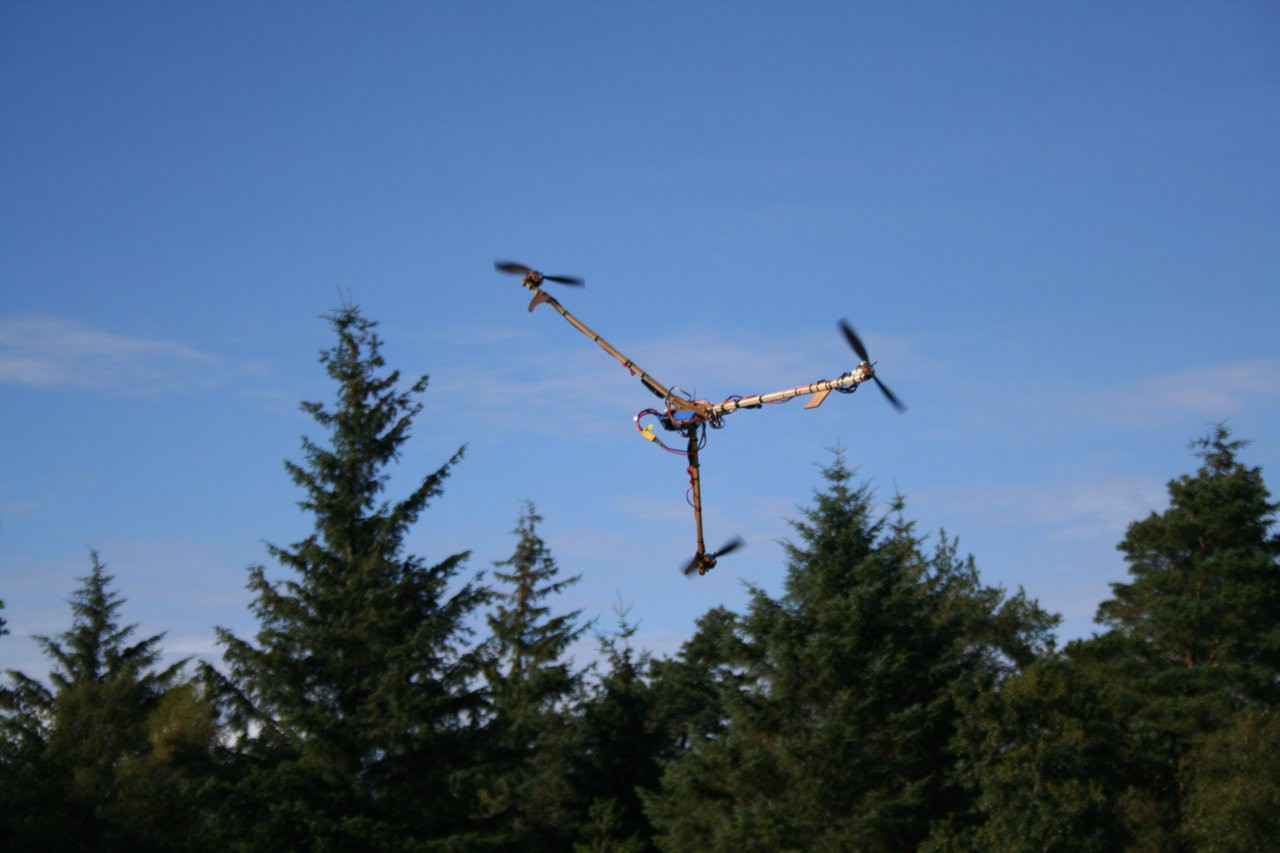
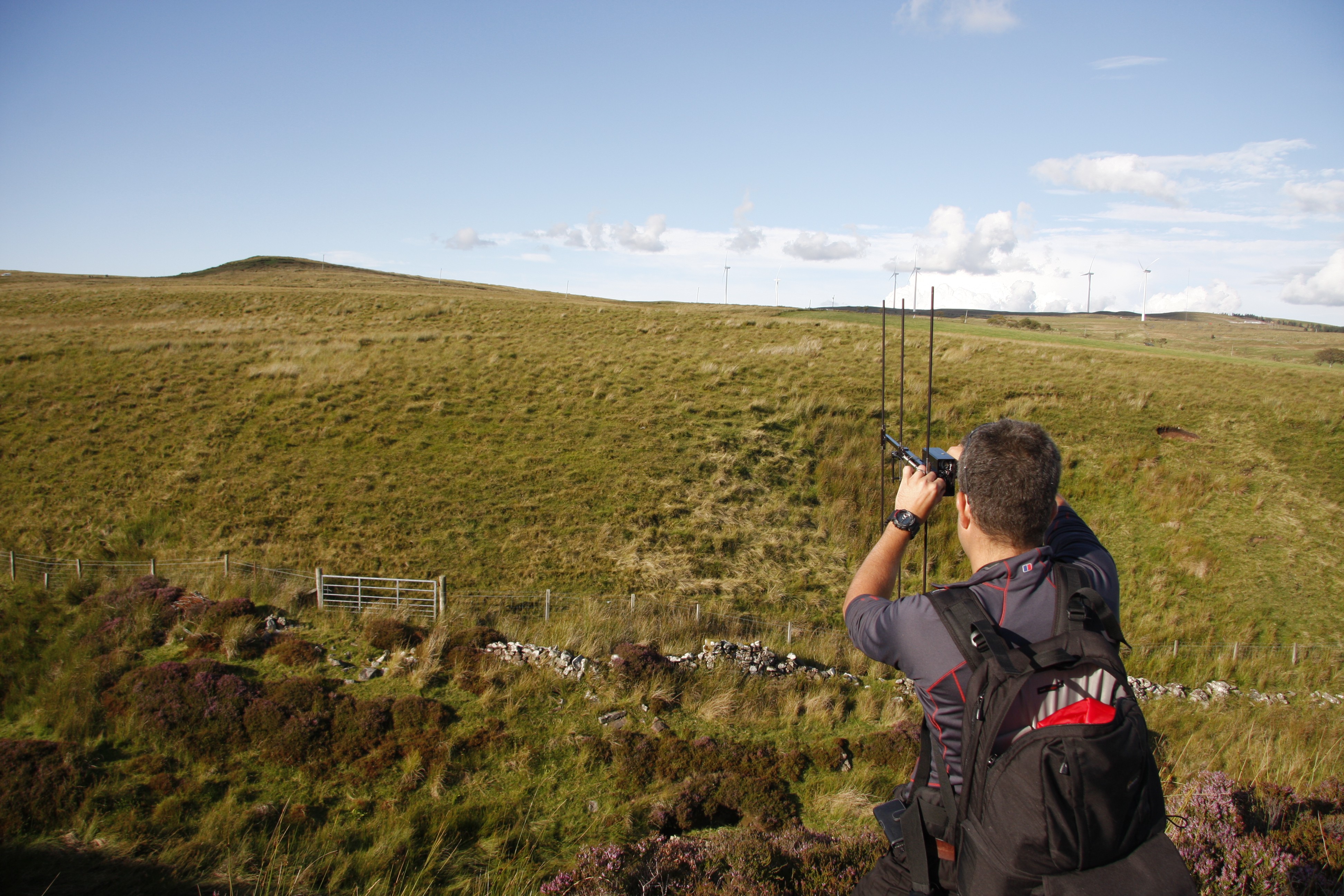
Hunting down a rocket on a Scottish moor using a Marshall falconry tracker system.

Amateur Rocketry Trackers
On a more personal note, radio beacons ("trackers") are commonly used in amateur rocketry, my main hobby. These make it easier to locate rockets after they have landed, as they can often travel quite a distance horizontally whilst descending under parachute.  Rocketry trackers also fall into two categories, those with GPS and those without. Whilst GPS is becoming more affordable by the day, non-GPS trackers still have the advantage when it comes to size/weight and transmission range.

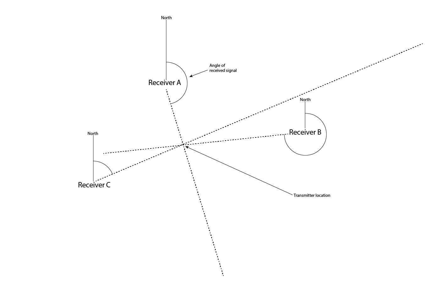
Rocketry trackers are found using traditional ham radio "foxhunting" techniques, with AM/FM radio receivers and a directional antenna. This is definitely a skill which improves with practice, and can be quite tricky if your rocket lands in an area with hills or ditches etc.

The problem with all of these systems is that, even with a reasonable idea of where the beacon is located, it can still take hours and many miles of walking to find it. Things can be done much more effectively if the search is performed using manned aircraft, but this is obviously an expensive proposition and may not always be available due to the location of the search or current weather conditions.

The Bloodhound Drone project aims to develop an autonomous drone payload which can assist with the search for a radio beacon and quickly give SAR personnel or trackers a more accurate location for their target.

But surely GPS-enabled beacons make this project unnecessary?
Actually, no - whilst GPS beacons are great, they do still have some problems which this system can help alleviate. Depending on the terrain around the beacon, the signal may not be able to travel very far horizontally. This is particularly true if the beacon is laying on the ground (among some plane wreckage, maybe); the range of the transmitted radio signal is very quickly eaten up by the ground. Having an aerial receiving platform helps solve this. GPS beacons are also reliant on the beacon having a clear view of the sky to get a GPS location. If it cannot determine its own position, you have to fall back to traditional radiolocation techniques to find the transmitter anyway.

Proposed Solution

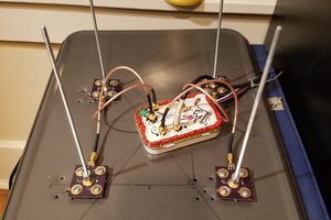
This project will create an electronics/radio payload for mounting on a drone (fixed-wing or multirotor as appropriate for the situation), which integrates with the Ardupilot autopilot platform to direct the drone to perform an aerial search for a radio beacon.

Initially, this project will focus on locating the beacons used in amateur rocketry, before eventually expanding to work with common EPIRB formats. Testing with rocketry trackers brings a number of advantages, as real EPIRB transmitters (understandably) have very strict rules governing usage and testing. Rocketry trackers can be used any time, any place, and amateur launch sites across the globe have a huge variety of environments and terrain.

It is certainly my hope that, in the future, this system could be used by SAR teams to speed up the process of searching for emergency locator beacons without using expensive manned aircraft. It appears...

Read more »

Rover Shelf APM.dwg

Shelf for mounting an APM2.6 + accessories to a Traxxas Stampede R/C truck.

DWG Drawing - 41.58 kB - 07/26/2017 at 15:00

Download

Frame v2 for APM.dwg

Upper and lower plates for an RCExplorer.se tricopter to mount APM2.6 + accessories (plus WIP additional shelf to mount Raspberry Pi + RTL dongle).

DWG Drawing - 37.90 kB - 07/26/2017 at 15:00

Download

View all 17 components

  • RF Heatmapping for Radiolocation?

    Phil Handley07/23/2017 at 23:46 3 comments

    Using a drone to hunt radio beacons opens up some radiolocation techniques which aren't necessarily available to a human tracker on foot. With the drone's ability to quickly and easily fly grid search patterns over any terrain, one possible radiolocation technique I'm keen to try out is generating an RF heatmap.

    RF heatmap showing WiFI signal strength in a building.

    RF heatmaps aren't a new thing, but they mostly seem to be used as a way of showing the signal strength of WiFi in a building, or cell network coverage. They're a way of visualising the strength of radio signals over a geographical area, with a colour scale to represent the strength of the signal at that point on the map.

    My plan is to fly a grid pattern over a given search area, and use an omnidirectional antenna mounted to the drone to take periodic measurements of the signal strength of the beacon. By pairing the measurements with the GPS coordinates of the drone, this should produce a map with a big red area showing the location of the transmitter. By using the stepped attenuator discussed previously to reduce the signal strength when close to the beacon, I'm hoping this technique should be able to provide a very accurate location for the becon.

    This should act as a complimentary radiolocation technique to the radio direction finding (RDF) techniques discussed in a previous log. The RDF techniques are best used when initially looking for the beacon - they should be able to determine a reasonably small area (few hundred square meters) in which the transmitter is located. When the drone has reached this area, the RDF may become overwhelmed by the signal strength and not be of much further use. In this case, the drone can switch to the omnidirectional antenna and begin flying the grid pattern to produce a heatmap.

    To see if this concept works as expected, I'm first going to knock together a system on my latop to test it out on foot. I plan to use a NavSpark Mini GPS reciever (and microcontroller), since there's already one plugged into my computer for another project, and an RTL SDR dongle. A small C program will periodically call rtl_power to take signal strength readings from the SDR, and retrieve the current location from the NavSpark, storing to a CSV file. I've had a look at the available heatmap generating libraries and none of them seem to do what I want, so I may well also have to write a quick script to generate a KML file containing the heatmap for use in Google Earth/Maps.

    Development of this test setup should take place in the next day or two, so stay tuned!

  • Stage 3: Build a Rover!

    Phil Handley07/23/2017 at 23:01 0 comments

    Because multirotor drones are terrifying, flighty, barely-controlled robots with spinning-blades-of-death on every corner, I decided that it would be a good idea to use something ground-based to test the more autonomous aspects of the project before they go on the drone.

    One of the fantastic things about the Ardupilot autopilot project is that, being a well-supported open source project, lots of variants of it exist using the same main codebase. In addition to supporting multirotors and fixed-wing aircraft, there is also a variant called Rover designed for autonomous ground vehicle platforms with great support for typical R/C car hardware. Building a rover not only allows me to test RDF techniques and hardware on a remote vehicle, it also lets me build experience and code for autonomous operations using the Ardupilot platform at the same time.

    My requirements for the R/C vehicle used here were pretty minimal - it had to be big enough to carry the APM2.6 + accessories, the Raspberry Pi + SDR and various antennas, and ideally be happy driving on grassy fields. A quick search on eBay brought up a pretty ancient Traxxas Stampede R/C truck for a steal and was quickly purchased. It arrived with a nicad battery, 27MHz R/C system, brushed DC motor and mechanical speed controller. These were quickly (and very cheaply - how did people afford this before Hobbyking?) replaced with the biggest 2s LiPo battery which would fit, an electronic brushed speed controller, and an FrSky 2.4GHz R/C reciever.

    After that nothing happened for quite a few weeks as it was actually quite a decent R/C truck, the sort I'd always wanted as a kid, and I was too busy playing with it to turn it into a rover!

    Eventually, I designed a mounting plate for the APM, GPS/etc and Raspberry Pi/SDR. This was cut out of 6mm plywood on a CNC mill, and fits on the body shell mounts of the truck. Antennas under test will be mounted on a wooden pole somewhere towards the front, probably with cable ties.

    So far it drives well with the R/C passthrough enabled on the APM. Unfortuntately I haven't had the time to take it out to an empty car park or field and play around with the autonomous functions of the APM yet, but am hoping to soon.

  • Radio Direction Finding Techniques

    Phil Handley07/23/2017 at 15:36 1 comment

    To be able to locate a radio beacon using the drone, the appropriate radiolocation technique needs to be determined. This log entry looks at the methods available and assesses their suitability for using with SDR on the drone, to find the best method to begin playing about with.


    Radiolocation Methods

    There are two broad methods for locating the source of a radio transmission. The first, Trilateration, uses multiple geographically-separated omnidirectional receiving stations while the second, Triangulation, uses one or more directional receiving stations.

    Trilateration


    The first method uses a technique called trilateration [wikipedia]. Each receiving station measures the length of time taken for the radio signal to reach their position, and when the times from three or more receiving stations are known, a position for the receiver can be calculated. The advantage of this method is that each receiving station is equipped with a simple, omnidirectional antenna (the received signal strength is the same from all directions), however you need multiple fixed receiving stations, and each station must be equipped with a very precise clock in order to have any accuracy (since we're timing things travelling at the speed of light here).

    Unfortunately, we only have a single drone, so this method is not much help (however the theory does come in handy a bit later). If you're interested in a trilateration radiolocation project, check out the MoSAReX project.


    Triangulation


    The second method uses the slightly more familiar-sounding triangulation [wikipedia]. It can be used with multiple fixed-position receiving stations, as with trilateration, or it can be used with a single mobile receiving station. The station is equipped with a directional antenna (the received signal strength is much higher when the antenna is pointed toward the transmitter), and determines the angle which the signal is received from. When this angle is taken from three or more different locations, the location of the transmitter can be calculated.

    The advantage of this method is that a single receiving station can be placed at each location in turn, and take a bearing to the signal. No clocks are involved, you just need to measure your position and the angle to the signal from a reference point (ie magnetic north) with reasonable accuracy.

    When using triangulation manually in real life, the operator would typically select 3+ good sites on a map (ideally at on top of some nearby hills), go to each location, take a bearing, and plot the lines on a map. As shown in the diagram above, the transmitter should be where the lines meet. This is the process I plan to implement with the drone, with the added advantage that we can select arbitrary points in space (as long as they're above ground) to take the bearings from!


    Radio Direction Finding (RDF)

    To get a bearing on a signal, you need a way to find the direction the signal was transmitted from - this is the field of Radio Direction Finding [wikipedia], which has had lots of development thanks to its use in aircraft navigation for most of the 20th century. Rather than looking at professional aerial navigation systems however, at this point we'll be going off into the world of amateur radio and the sport of "Foxhunting" [wikipedia]. Not surprisingly, radio nerds have made a sport out of searching for hidden radio transmitters and dedicate quite a bit of effort to the equipment they use to help them.

    Again, there are two main methods of RDF used in the foxhunting world - using a directional antenna (a "directive gain antenna" to be more precise), or using a direction-finding (DF) system.

    Directive Gain Antennas

    Radiation pattern of a typical Yagi antenna (ignore the Russian!) [wikipedia]

    As the name suggests, directive gain antennas achieve their directionality by applying gain (increasing the recieved signal strength) in the direction the antenna is pointing. Think of this in the same way you can focus the light from a lightbulb...

    Read more »

  • Stage 1: Build a drone!

    Phil Handley07/22/2017 at 23:35 0 comments

    So Stage 1 of the project is to build a drone - kind of hard to create a beacon-hunting drone system if you don't have a drone to test it with.

    I'll admit right away, this stage of the project has taken waaayy longer than I originally thought it would. Building drones from scratch can be quite a learning process, especially if you've never even flown one before!

    Starting with a multirotor rather than a fixed-wing seemed to be the obvious choice for developing the RF payload - the ability to hover at a given point in space and have precise control over the direction the drone is pointing in should come in handy during the latter stages of development. Instead of a more traditional quadcopter, I decided to go for a tricopter (three motors/propellers). Firstly I think they just look really cool, but the wide spread of the arms should give lots of room for mounting antennas and the servo on the rear motor provides really good yaw control, for pointing all those lovely antennas. Also, budget being a concern, three sets of propellers/motors/ESCs costs less than four sets, right?


    I used the RCExplorer.se Tricopter v2.5 design as a starting point - I really like the build method and the way it's designed to crash cheaply (vital when learning to fly!), using cable ties to create weak points instead of damaging more expensive components. The way the front arms fold back for transport/storage is also really useful. Using the DXF files RCExplorer has published, I laser cut the frame and legs from 3mm plywood and used hardwood square dowel for the arms.

    Originally I built it exactly as per the build instructions, including the KK2 flight control board. After trying to actually use the board, I quickly crashed the tricopter and chucked the KK board away. This was replaced with a Flip32 running Cleanflight, which worked a lot better and let me learn to fly, but still wasn't great.

    (As a side note, I wouldn't recommend building your own drone as a first drone if you don't already know how to fly. When you're first learning with a home-built drone it gets very difficult to know if wobbles and instabilities are caused by your build being bad, by the PID tuning not being correct, or if you're just a terrible pilot. Or all three at once.)

    After I was able to pilot the thing without crashing, I swapped flight controllers again and replaced the Flip32 with an Ardupilot APM2.6 autopilot. While the previous two controllers had no autonomous capabilities (just enough to stabilize it), the APM has GPS and enables the full range of autonomous autopilot functions. Switching to the APM, even with stock PIDs, showed a night-and-day difference from the Flip32. The flight stability was much better, and the position hold/return-to-home functions just worked straight out of the box.

    The APM2.6 was great and did almost everything I needed. Apart from one thing - there was only one MAVLink serial interface to the autopilot, and this was used in flight by the telemetry radio, which is used to receive telemetry on a laptop and provide commands such as "Go to this waypoint" on the fly. But in order for the Raspberry Pi companion computer used in the radiolocation payload to control the autopilot, a MAVLink interface is required. After spending a while messing about with an ST Nucleo mbed dev board to act as a sort of MAVLink multiplexter/injector between the APM, Raspberry Pi and telemetry radio, I noticed the price of Chinese Pixhawk flight controller clones had dropped quite a bit, so I upgraded flight controller yet again. The Pixhawk runs the same Arducopter firmware as the APM2.6, but has three MAVlink serial ports on it, among many other improvements.

    I won't go into too many details about the Tricopter build, as it's the RCExplorer Tricopter with a pretty standard Arducopter setup mounted to it. One thing that did require deviation from the RCExplorer design is the design of the top frame - I extended this and added mounting holes for the...

    Read more »

View all 4 project logs

Enjoy this project?

Share

Discussions

Thomas wrote 11/05/2018 at 02:11 point

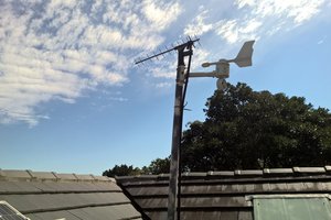
I'm interested in developing a similar concept to create a search and rescue drone that would track wifi in cell phones in areas with little or no cell tower coverage.  Basically I'd have the drone send out a wifi beacon frame matching a SSID known to the missing person's phone and that would cause it to continuously try to handshake with the drone.  Most of this would be identical to what you are doing. Have you made progress in this project since last year? 

  Are you sure? yes | no

Daren Schwenke wrote 08/28/2017 at 14:55 point

Four of these on a pcb as your antenna?  YAGI antennas without a lot of math will only work well for one frequency.

https://en.wikipedia.org/wiki/Vivaldi_antenna

  Are you sure? yes | no

equinitry wrote 08/25/2017 at 14:07 point

Looks realy interesting. Some time ago i did some personal research on RDF and its difficult^^ It depends what you wanna do and what you want to track and how much money/effort you want to put in. Practicly one of the accurate and easiest solutions is the Yagi approach. But its not good if you have very short or broad signals. If you do the rotating antenna approach and do some measurements on different positions it will be nice, but you need a lot of antenna and electronic stuff (antenna switching etc) and of course dependend on the distance, accuracy, amounts of antennas, distance of antennas you need to have a high switching frequency and then you get some other problems. The TDOA idea with 2 antennas might be good but its basicly the same as with rotating antennas (only that you have 2 instead of 4 or more).

If you want to do SDRDF, do you think about using the movement of your drone and use its doubler frequency? If it is a continous signal than it will be easy applied:

For example a beacon with a frequency of 20 MHz and the drone moving in on direction with 3.6 m/s gives a shift, depending on the orientation, from +-670 Hz and you dont need any extra fancy circuits/antennas etc.

f(measured) = f(no movement)*(v*cos(alpha)/c(lightspeed))

-->get angle from shifts

1. Stop and measure frequencys

2. Move in on direction and measure shifts

3. Move in another direction and measure shifts

4. Combine directions and determine origin of signal

pros: omnidirectional antenna, no extra circuits etc needed, multiple frequency measurable

contra: only works for time constant beacons (no fm modulated signals)

edit: read a bit more of your aims, guess it all depends what signal do you have and how accurate it should be. Lot of emergency beacons etc only transmit in bursts to save battery. Since multiple antennas are not adequat for a drone you could use the drone as a mobile antenna. Its kind of TDOA approach, use the gps clock to determine the arrival of a signal between two drones or one drone and one ground station. Ideally you crosscorrelate the two received signals, determine time differences, translate it in angular intensity and move to the next location and wait/measure again.

This should work with great accuracy if the beacon is not moving because you can have great distance between the two drones which give a greate benefit.

xD well got some more ideas but it all goes down what you want to track and how much money/effort you want to investigate

  Are you sure? yes | no

Phil Handley wrote 09/03/2017 at 23:20 point

Wow, lots to think about here, thanks! Gotta love HaD commenters! Apologies for the delay in replying, been really busy travelling and then moving house.

The Yagi approach is certainly tempting with it's ease, but they are rather bulky so I'm going to keep that as a backup option for now. The short duration of most beacon transmissions is, as you say, one of the complicating factors here but I'm hoping to be able to get the SDR to lock the rest of the system to the transmission pulses, so bearings etc are only taken when transmissions are actually occurring. Or at the very least readings when it's not trasnsmiting are discarded on the fly.

I think a traditional flying doppler RDF setup is possibly the best option here, it's not an outrageous number of antennas to mount to a drone (and way less ungainly than a decent yagi antenna) and the electronics aren't too complex if you're incorporating SDR into the system (check out http://wiki.spench.net/wiki/SDRDF). The instant bearing calculation makes it easier with the short duration of the beacon transmissions, and means many many bearings can be taken whislt flying in any direction without worrying about the orienation of the drone, which is particularly ideal for a fixed-wing platform.

I love the idea of using the movement of the drone to create the doppler shift, that is something I had not considered at all. Unfortunately I think there might be an error in your maths somewhere, the equations given at https://www.microwaves101.com/encyclopedias/doppler-shift show the doppler shift of a 20MHz signal at 3.6m/s as roughly 0.24Hz.
Using 18m/s as a guess at a max speed for a drone bristling with antennas, at VHF this gives a ~9Hz shift and at UHF a ~26Hz shift. I'm not sure these shifts are out of the question for a decently expensive SDR, but I'm guessing not so good for an RTL dongle. I'll have to dig up the frequency stability specs for some of the higher end SDRs and work out what sort of error we're looking at in terms of direction finding.

Could be a good excuse to build a supersonic beacon-hunting drone though! ;-)

Trilateration with TDOA is an option, but I'm hoping I don't have to be super accurate with the initial transmitter location taken from a distance - my plan is that once a rough estimate of transmitter location is taken, the drone can fly to that locaiton and then begin a quick grid search of the area to produce a heatmap which should pretty obviously show where the transmitter is - if people on foot haven't already found it by then.

Thanks very much for the ideas, really appreciate it - do let me know if you have any more thoughts!

Cheers,
Phil

  Are you sure? yes | no

equinitry wrote 09/04/2017 at 14:24 point

Oh yes youre right, somewhere i made a mistake (like 1e3) xD

With 10 m/s its only for high frequenies applicable i guess (depending on the resolution of the dongle)^^

f(20)=+-0,67Hz, f(121,5)=4,05Hz, f(406)=13,54Hz.

Yagi antenna wouldnt fit good for burst sending beacons (and if im not wrong, EPIRB only sends every 60sec). The TDOA approach is, i guess, the most challenging but also it should be the most accurate solution. The rotating antenna (or more precisly phase interferometry) is also very nice, but takes high payload with antenna and the handling for the switching circuit is also not trivial (the more antenna, the higher the switching frequency...and also get switching artefacts). I read  recently a blog article where someone build a SDRDF by using 8 single antennas in a circle each connected to a single RTL dongle (because theyre so cheap^^) and so dont have to switch the antennas but only correlate the signals xD.

Guess youre right, that two dipol antenna switching (phase interferometry) might be the best solution for a autonomous drone. Correlating the switching frequency with the received "sine"-signal (not realy a nice sine wave with 2 antennas to be excpected xD) could give a satisfactorily accuracy after calibrating. Since youre only having two antennas PIN Diodes might be okay but there are also some nice semiconductor RF switching ics for multiple antenna with good (even better) characeristics then constructing your own switching circuit with PIN diodes.

Another thing i was thinking about is "why not using a blimp instead of a drone?". With a blimp you dont need such a big accu, have much longer airtime, big antenna can be easy fit to the shap of the blimp (maybe directly print on the blimpshell with copperfoilt for example and you can easily use more than 2 antennas), less/no interferences from motors. You can lift with 1m3 H2 around 1,2kg (i suggest to use H2, cheap and can be produced almost everywhere out of water).

keep us updated, im realy curious how the project is developing and sorry for my bad english xD

edit: i think ultrasonic beacon is not a good idea, no long range (should be infrasound xD like the elephants) and think of the poor animals like bats etc.

  Are you sure? yes | no

Daren Schwenke wrote 07/31/2017 at 20:31 point

This is a fantastic idea and I'm looking forward to seeing it progress.

  Are you sure? yes | no

Phil Handley wrote 08/01/2017 at 10:47 point

Thanks Daren! Hoping to put a decent amount of time into this over August so hopefully there should be a bit of progression by the end of the month.

  Are you sure? yes | no

Similar Projects

Does this project spark your interest?

Become a member to follow this project and never miss any updates