 Martin
Radio direction finding (RDF), T-hunting or fox hunting has been a hobby in the ham radio world for a long time. If you've ever seen a car equipped with a big, crazy looking antenna, a square antenna array or people running around with funny antennas and radios, they are probably T-Hunting. If it's a weekend it's probably hams and on a weekday it's someone looking for a transmitter for another reason.
T-hunting is still a thing with communities of hunters. In San Francisco there is rdf-sf and there may be a club in your neighborhood. http://www.homingin.com is a great source for fox hunting information and LA area hunts.
Google is your friend for Doppler Direction Finding theory of operation. The May and June 1999 QST issue with WA2EBY's article on a radio direction finder is based on simulated Doppler. For even more information find a copy of "Transmitter Hunting - Radio Direction Finding Simplified" - available in dead-tree form only. The 1999 article is an update to WA4BVY's early 80's design. It's been 20 years so a technology update is overdue.
The WA2EBY DDF system consists of an antenna array, an antenna switch and controller/display composed of nine chips (74HC), a couple of transistors, a voltage regulator and a bunch of passive parts. The controller electronically "rotates" the antenna array by sequentially switching one antenna on after another in a circular fashion. The switching imparts a Doppler tone FM modulated on a received signal. WA2EBY's design used cheap 1n4148s for switches - at the time PIN diodes could be over $10 and the system needs 8. PIN diodes have become commodity parts and the BAP64-03 PIN diodes I'm using are $0.09. In addition the 1n4148 are rated for 75 V and the PINs are 175 V. The WA2EBY design rotates the array at a fixed 500 Hz but I have designed mine to have a variable Doppler frequency from 2,000 Hz down to whatever. The controller uses a switched capacitor filter to make a very narrow band signal to measure phase. An analog zero crossing detector was used to measure the time from an antenna switching to derive the Doppler phase angle and signal Angle of Arrival.
My update is based on a Teensy to replace random logic. (Originally using Teensy 3.2 - now a 4.0). At first the Teensy Audio Library was used to replace the switched capacitor filter with a narrow digital filter and an outboard comparator was used for the time difference measurement. I have found that approach limited in accuracy. I an now working on a "DSP Version". The big motivation is the elimination of considerable hardware and performance improvement. The filters are implemented with the Goertzel algorithm which is a simplification on computing DFT bins on the frequencies of interest.
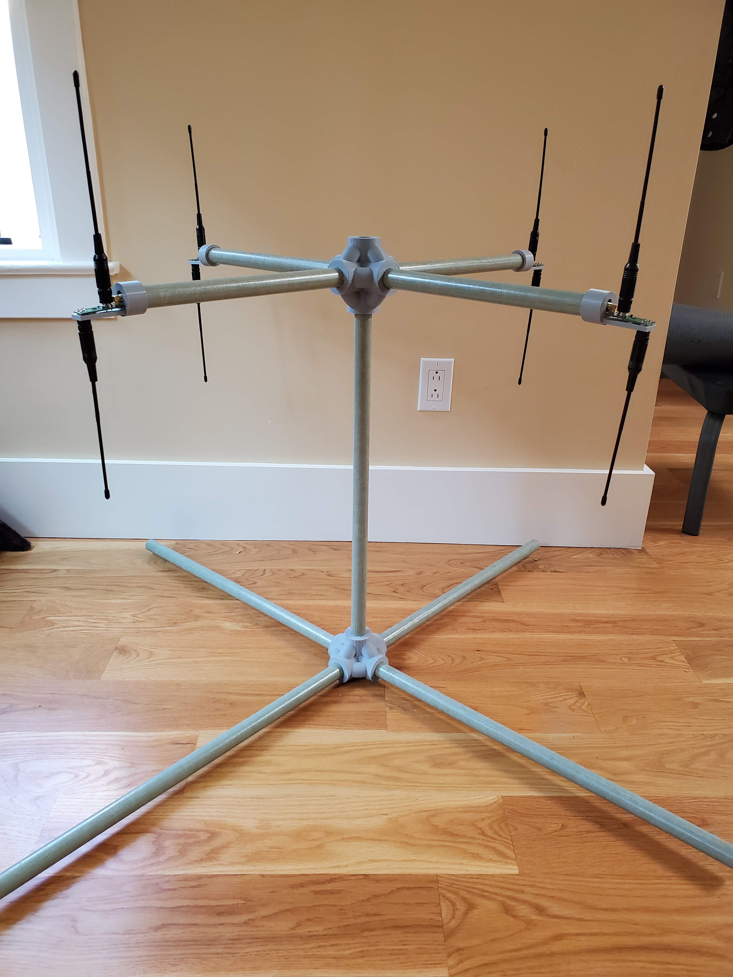
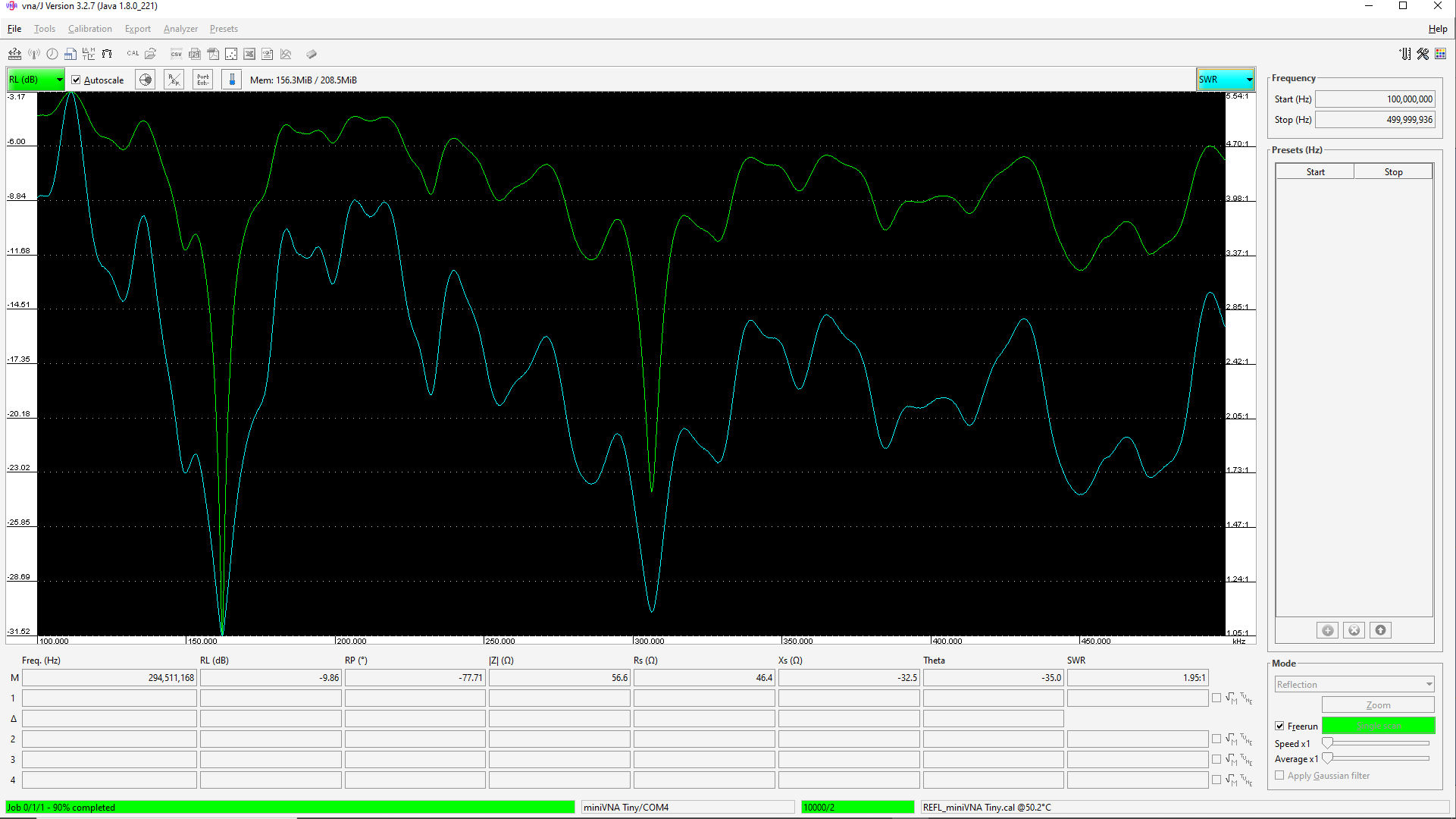
One problem I ran into was the lack of metal on top of my cars. The enormous glass sun roof's lack sufficient metal to be a useful ground plane. I am now building a vertical dipole array. It is electrically working on VHF and needs to be sturdier before driving with it.
The Neopixel is a nice update of the '80s ring of plain old blinken' LEDs. A single white pixel points direction and the rest of the array displays signal quality. There will be a heading readout.
Testing - I am using a cheap 0.5 W FM transmitter module for a test signal. I fired everything up and the display was crazy random. I have come to learn that was to be expected. I am testing in a small office with metal filing cabinets so there are lots of reflections. Even my movement in the office makes a difference. I did some testing on the major functions and everything looks right. I wanted to test with a RF signal generator that somehow was synchronized to the antenna...
Read more »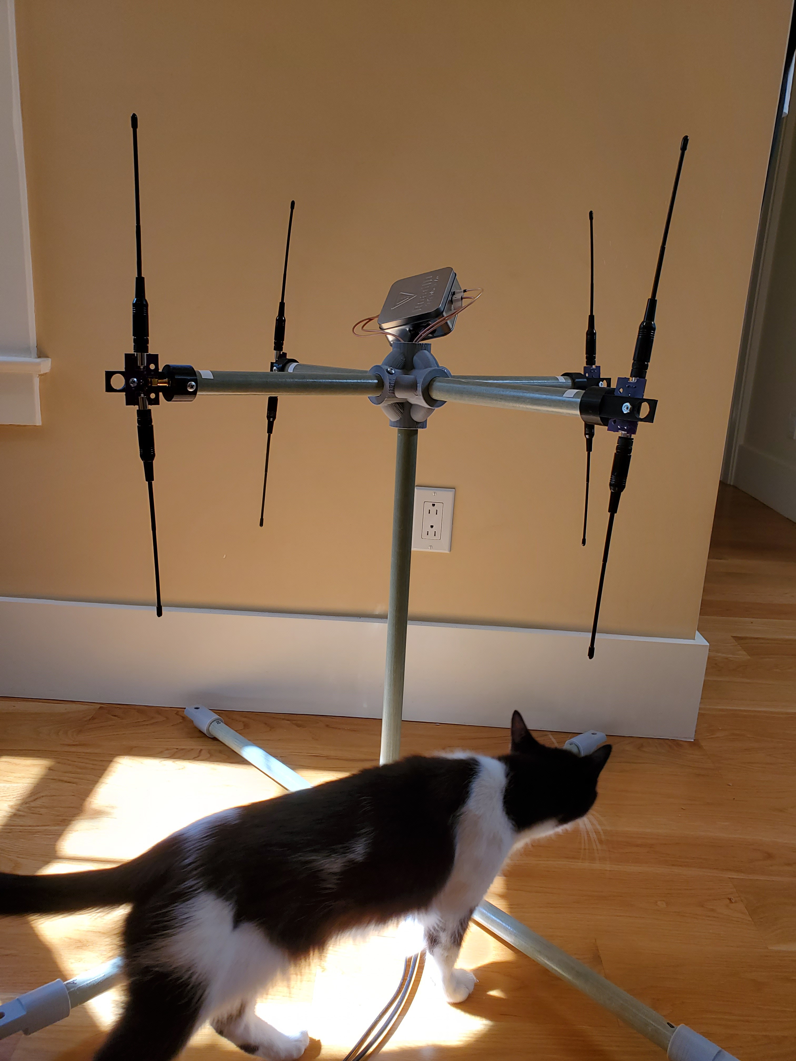


 W5VO
W5VO
 Phil Handley
 Capt. Flatus O'Flaherty ☠
 2FTG
2FTG
"if you have a [logic/analogue/ghetto-RF] problem, if no one else can help... and if you can find him... maybe you can hire...
@Ted Yapo"
...cue theme tune.