 Rui Caldas
INTRODUCTION
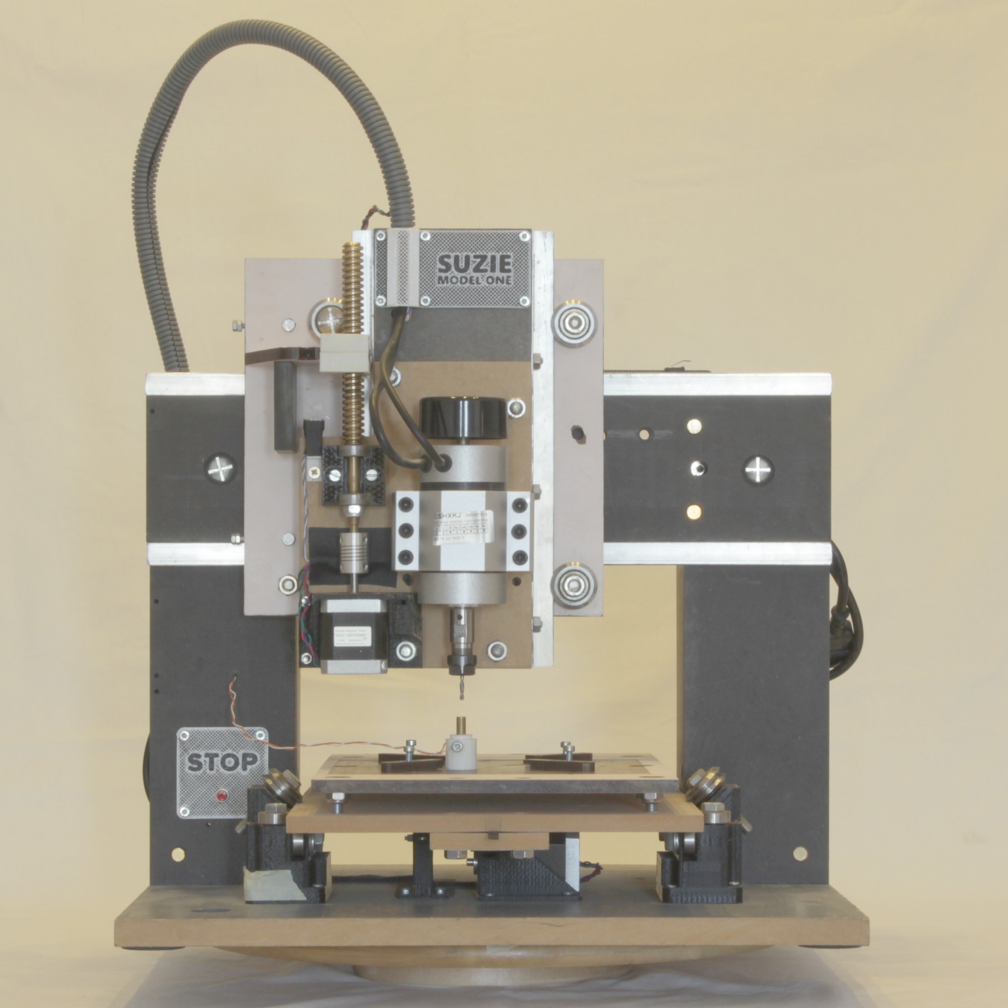
The SUZIE MODEL ONE is a 3-axis CNC machine specifically designed for cutting PCBs. The primary goal was to develop a machine that is both rigid and accurate, with as much automation as possible. Currently, the only manual operations required are changing the cutting tool and positioning the Z-probe correctly.
This machine is the product of an iterative design process, involving the redesign and reconstruction of various parts to achieve optimal performance. One of the main challenges encountered was ensuring rigidity: insufficient rigidity can cause the machine to bend during cutting, leading to failures. Another significant issue was minimizing jitter when navigating corners. While reducing the speed can help address this, it is not always ideal since some cuts perform better at specific speeds, and efficiency is crucial.
For more information and updates, check #suziecnc on Instagram.
The following chapters will detail the reasoning behind various design choices and, where applicable, the specific problems these decisions address.
DIMENSIONS
External Size:
- Width: 46 cm
- Length: 62 cm (43 cm excluding non-working areas)
- Height: 58 cm (including the cable tube)
Working Area:
- Width (X-axis): Approximately 20 cm
- Length (Y-axis): Approximately 20 cm
- Height (Z-axis): Approximately 6 cm
FRONT VIEW
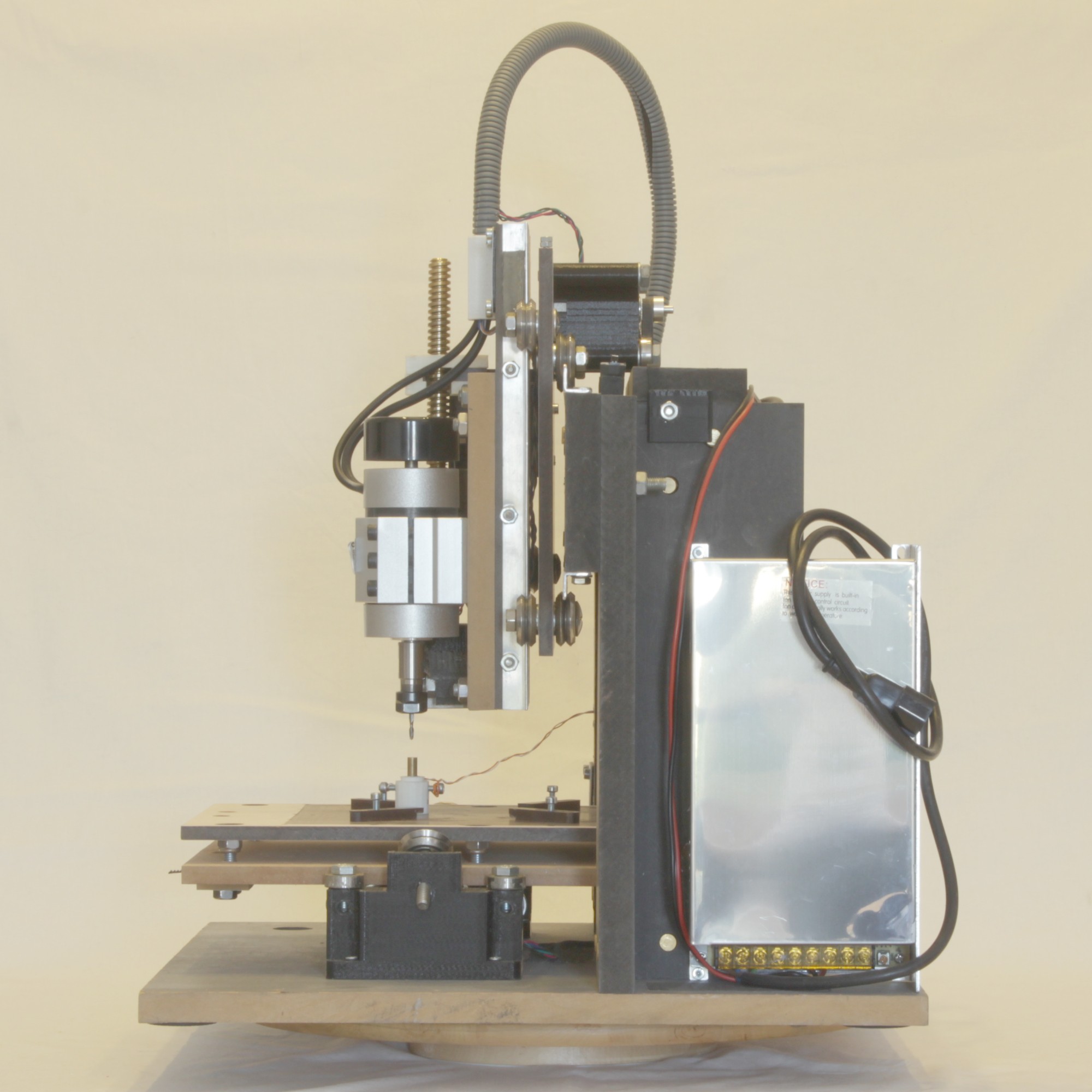
LEFT VIEW

RIGHT VIEW
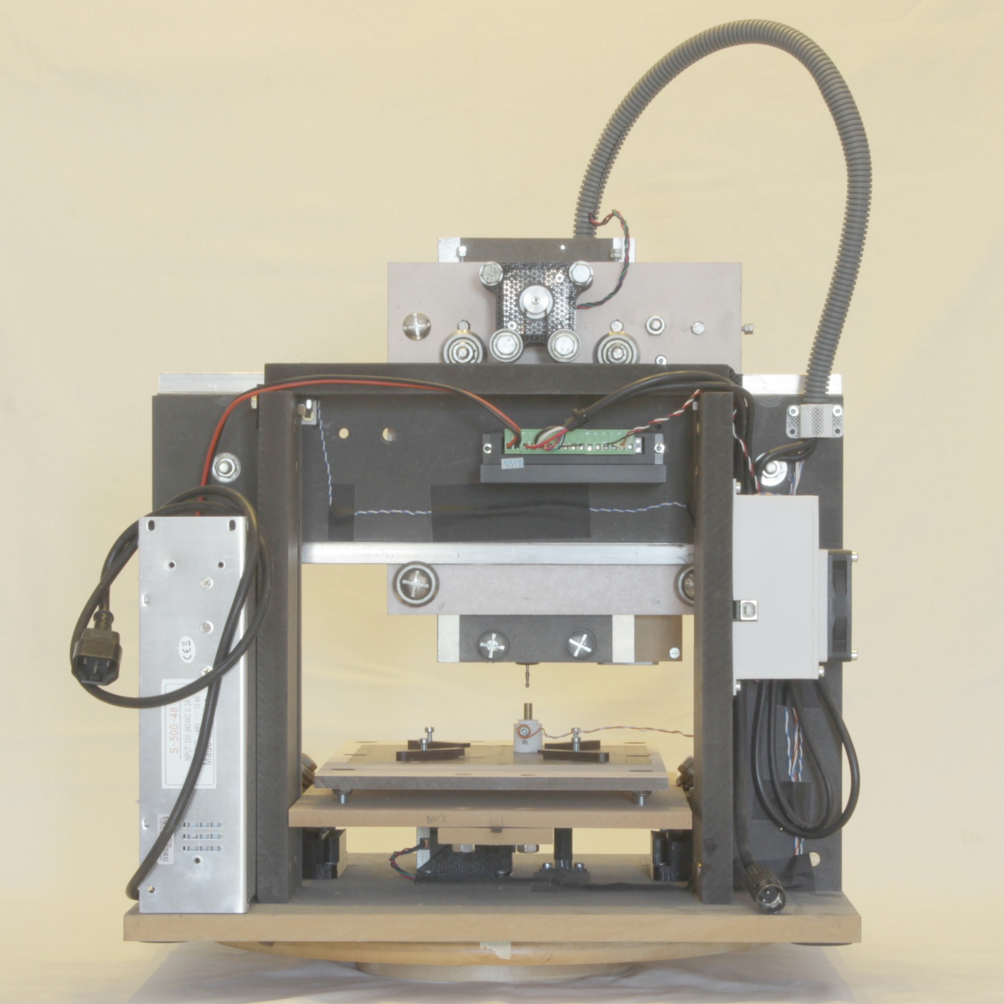
BACK VIEW
TOP VIEW

XY AXIS, STEPPER MOUNTING AND BACKLASH
Backlash is defined as "...a clearance or lost motion in a mechanism caused by gaps between the parts..." (Backlash, Wikipedia).
The SUZIE MODEL ONE boasts zero backlash on both the X and Y axes. This precision is achieved without firmware compensation, ensuring accurate cuts every time. This is made possible by utilizing belts instead of lead screws. Lead screws inherently require a small gap to operate within the nut without friction, which must be compensated for. While this compensation can address initial backlash, over time, wear on the nut can introduce constant backlash that needs to be configured in the firmware. However, if the lead screw itself wears unevenly—due to varying speeds and forces along different segments—compensation becomes more complex and less effective.
The belts used in SUZIE are robust enough to apply significant force, even for metal cutting, and when properly tensioned, they exhibit negligible elasticity.
Both axes in SUZIE employ the same technique for transferring force from the stepper motor to the moving parts, with a notable difference in the mounting of the belt and stepper motor. Unlike typical 3D printers where the belt forms a loop in a larger mechanism that occupies more space, in SUZIE, the belt is open and fixed at both ends, with the stepper motor moving along it like a rack and pinion system.
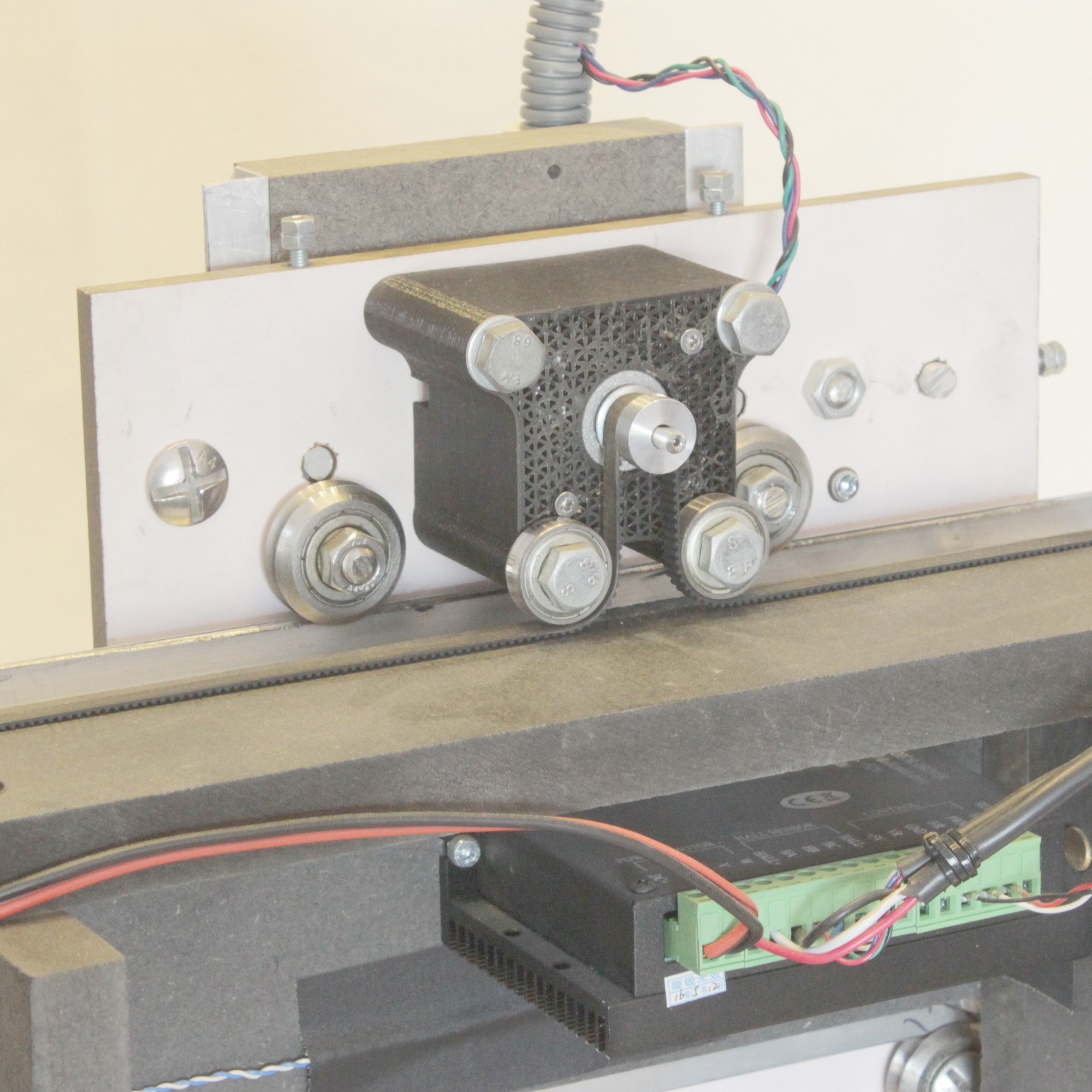
On the X-axis, the stepper motor is attached to the carriage, and the belt is fixed to the machine. As a result, the stepper motor moves with the carriage.
X STEPPER AND BELT
The Y-axis tray employs the same concept as the X-axis but in reverse: the stepper motor is fixed, and the belt moves. This design allows for a virtually infinite Y-axis length, which can be adjusted as needed without altering the overall machine design. This flexibility is possible because the rail is mounted on the moving tray, and the bearings are fixed to the base of the machine structure.
Y TRAY WITH BELT (view from the bottom)
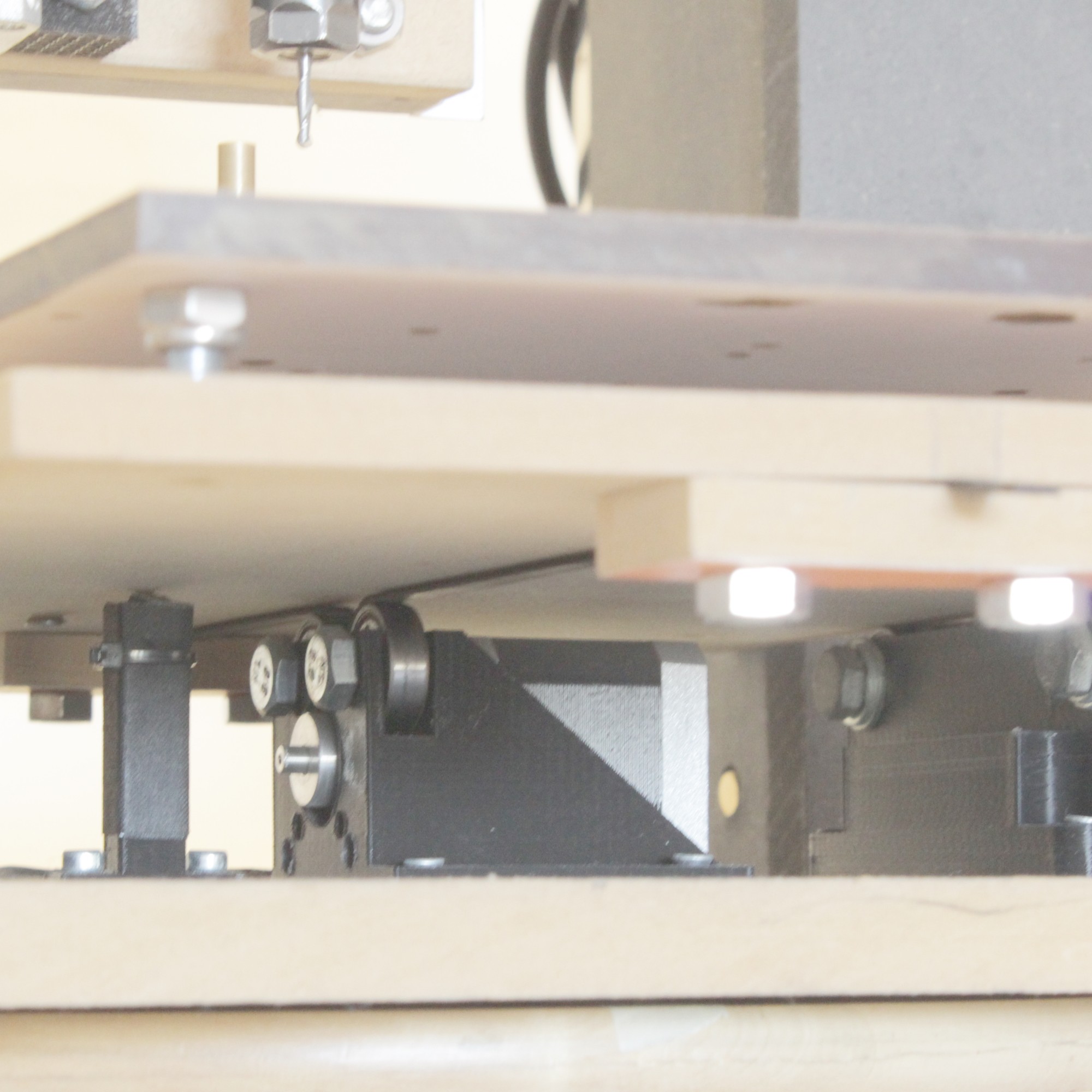
Y TRAY BEARING SUPPORT
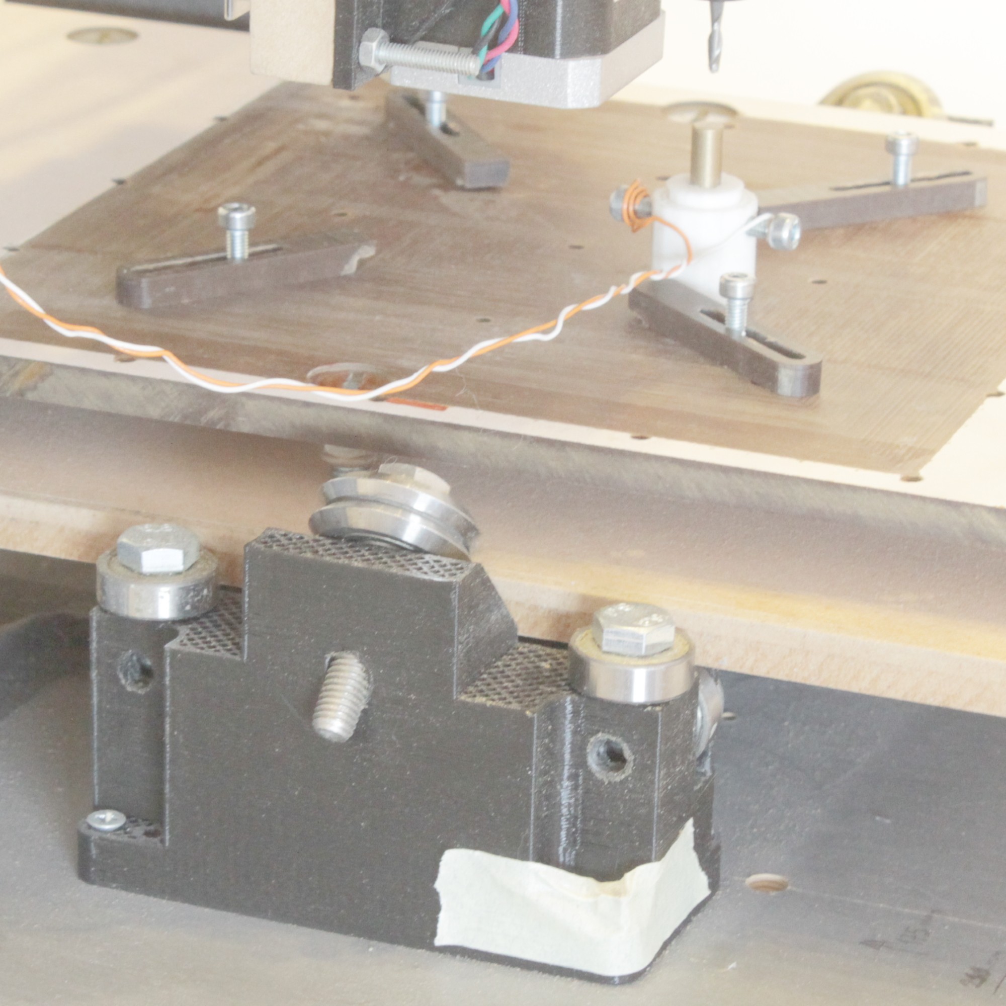
This picture shows the Y-axis bearing support part. This is the left side bearing support and there is another on the other side.
This bearing supports are aligned with the X-axis carriage movement and positioned directly below the spindle center. This alignment ensures that all downward and lateral forces are transmitted to the base in a compressive manner. This design allows the support to be extremely rigid and capable of sustaining significant forces.
As illustrated in the picture, the length of the Y-axis tray is not a critical...
Read more »
 NPN
NPN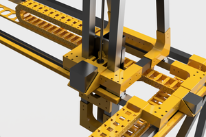
 Brian Brocken
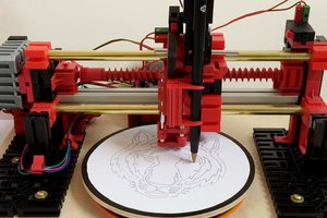
 davidatfsg