0%
0%
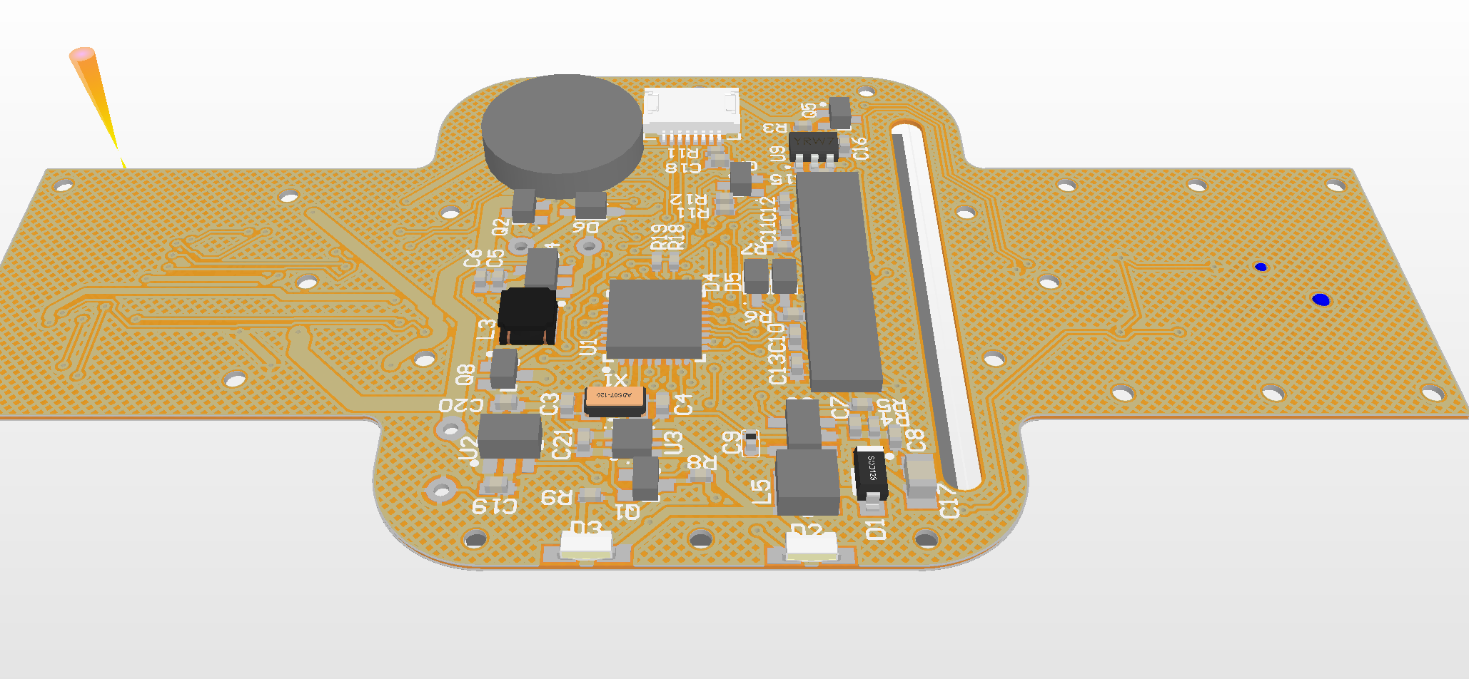
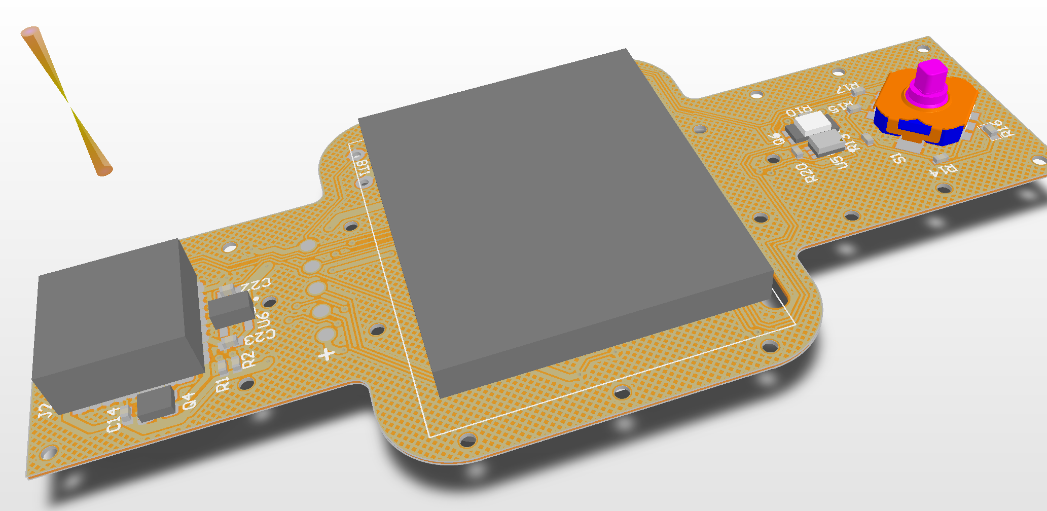
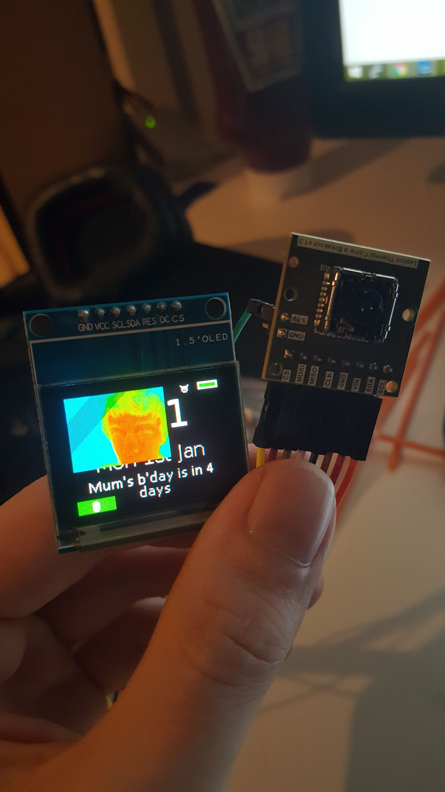
Thermal Watch
An attempt to design a watch that integrates a thermal camera, whilst remaining sleek.
 Joshua Elsdon
Become a Hackaday.io member
Already have an account? Log in.
Just one more thing
To make the experience fit your profile, pick a username and tell us what interests you.
Pick an awesome username
hackaday.io/
Your profile's URL: hackaday.io/username. Max 25 alphanumeric characters.
Pick a few interests
Projects that share your interests
People that share your interests

 greg davill
 Dimitar
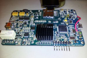
 charliex
 Sagar 001
Really neat project!