 Nicholas Hill
Parts were a mixture of ordered and had on hand.
Pricing is going to be totaled later when I'm done because I keep buying more things.
Gameboy handheld form factor capable of playing all emulation up to about a Playstation 1. I've been calling it Cubone.
Already have an account? Log in.
To make the experience fit your profile, pick a username and tell us what interests you.
Parts were a mixture of ordered and had on hand.
Pricing is going to be totaled later when I'm done because I keep buying more things.
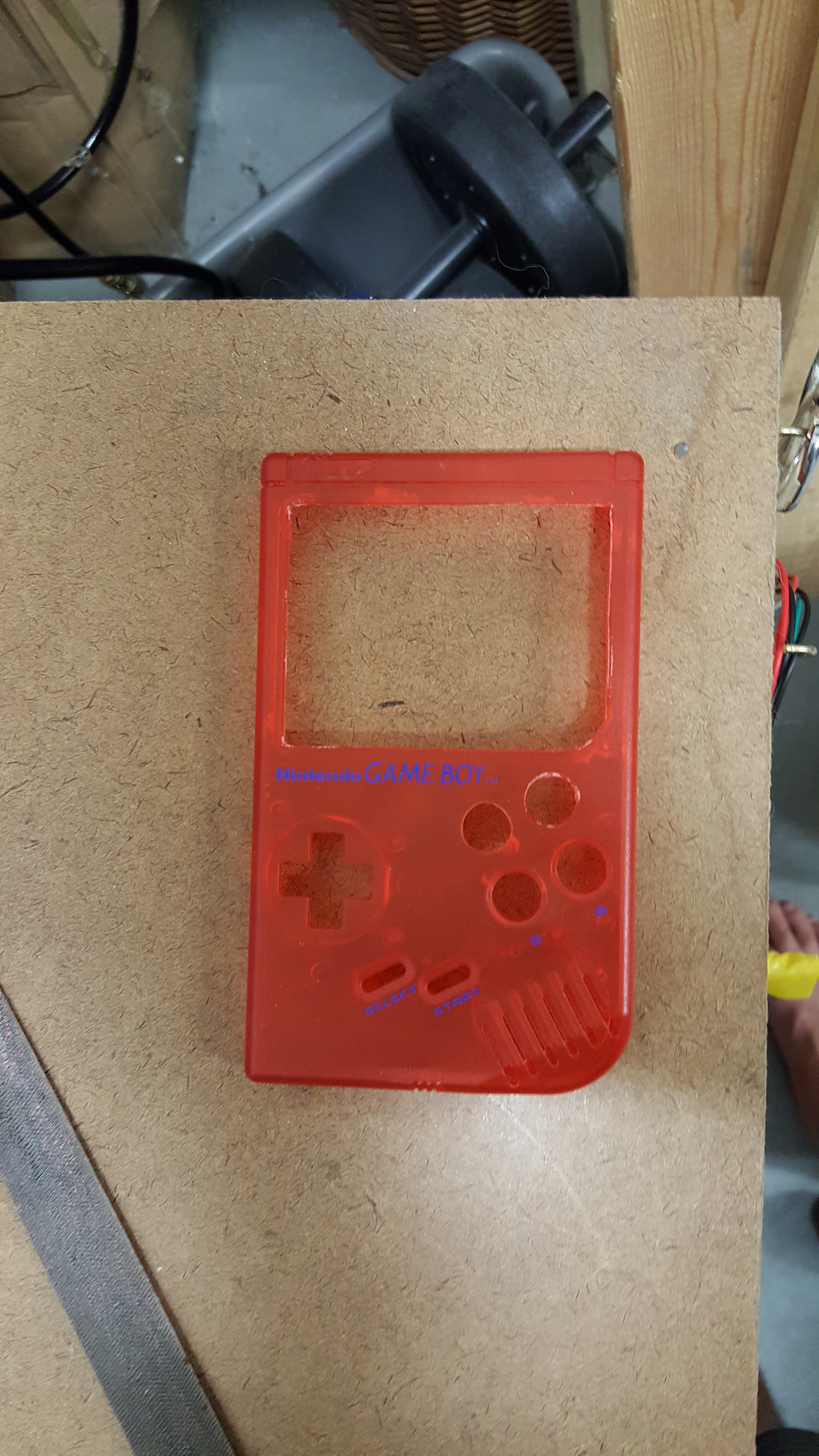
20170817_113333.jpgCase arrivedJPEG Image - 4.03 MB - 08/17/2017 at 15:36 |
|
|
Alright, semester is winding down! Got 3 finals in the next couple of weeks then it's back to me time for a couple of weeks. I have braided copper wires hopefully in my mailbox today to rewire the entire project because the solid copper wires are putting too much force on the pi and control board whenever I move them and I get a lot of solder breaks as a result. I also am redoing the thumb buttons (specifically the x and y buttons) to make them click better like the A and B buttons. I need to put in some option for an escape key, and also somehow a graceful shutdown command to the pi board. I keep loosing my config file because I get into a game, and have no way to back out to the main menu to shut down the pi. Also the caps for the audio filter came in, so we can make a low pass filter for the audio to get rid of some of the processor noise. A lot of this will be done after the 13th, with logs as we go. A lot of people (relative to me) have been seeing this project, so I want to get it finished up and cut out some instructions for it when I'm totally finished so hopefully someone else can make them one too without as much hassle.
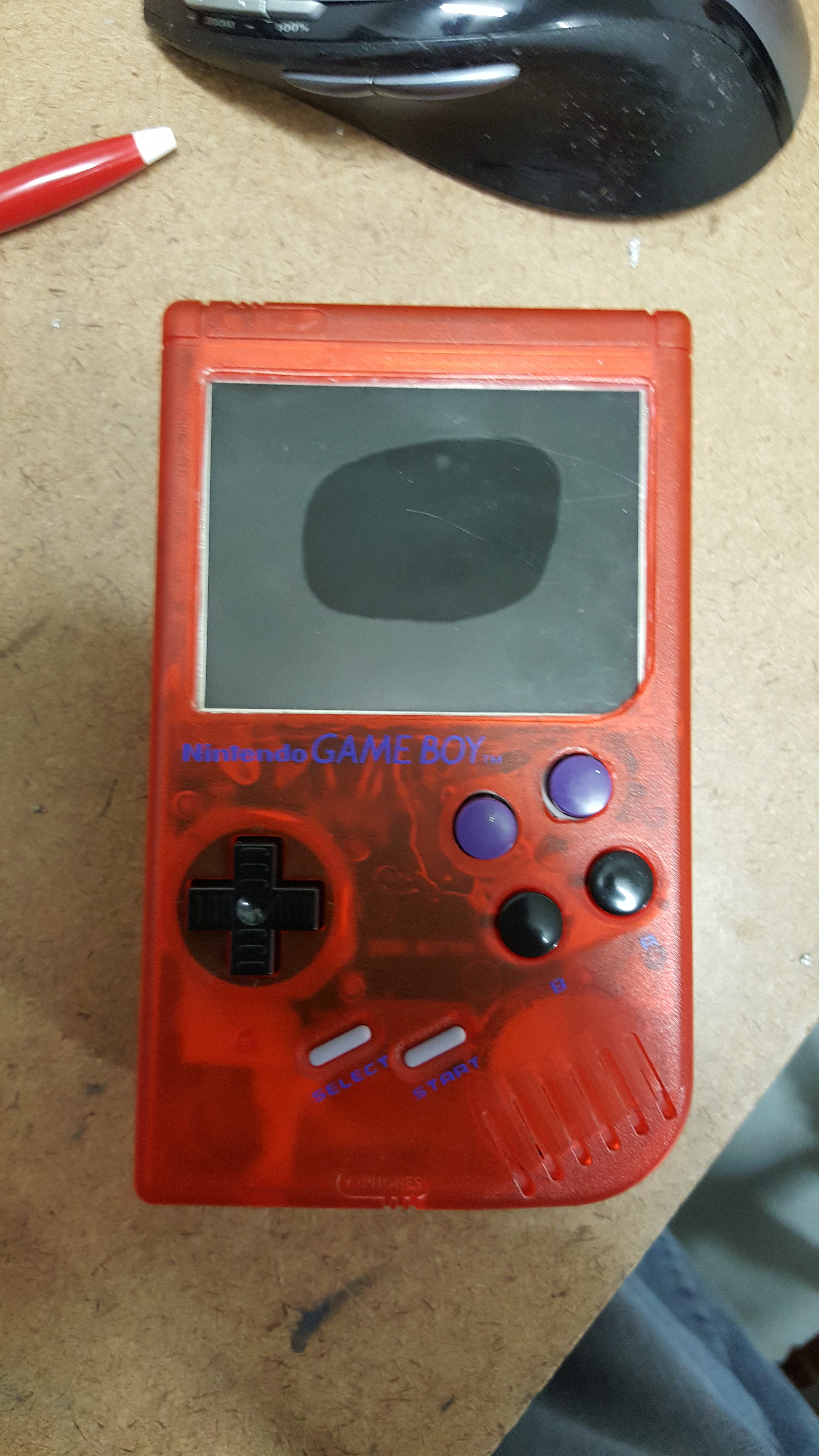
Okay. So the buttons for the X and Y functions are not working out. I reordered some of the silicone button pads and am redoing how the buttons are held in place. The A and B buttons are great, this is basically going to make the X and Y identical functionally. This involves some fun dremel work to grind down the grey button bracket to just two small plastic arcs for each button. This will make them sit evenly with the AB buttons and allow the silicone button pad to be mounted behind them.
Also if you're starting this project, don't use solid copper cabling for the wires. Use braided copper for god sakes. The solid copper wires are just too damn stiff and keep breaking out of the solder mount holes on the pi and the controller board. Really aggravating.
The audio is having some issues getting sound out at all, all I can hear now is the induced processor noise. A Low Pass band filter is being made, the capacitors just came in yesterday. On a happy note today is the start of fall break so hopefully I can get some time in actually working on it.
Finally, I'm adding in a separate button to kill the pi before I kill power. I keep losing configurations etc due to the controller board not working correctly and having to shut it down by simply dropping power. This is really bad for the OS and also aggravating for troubleshooting.
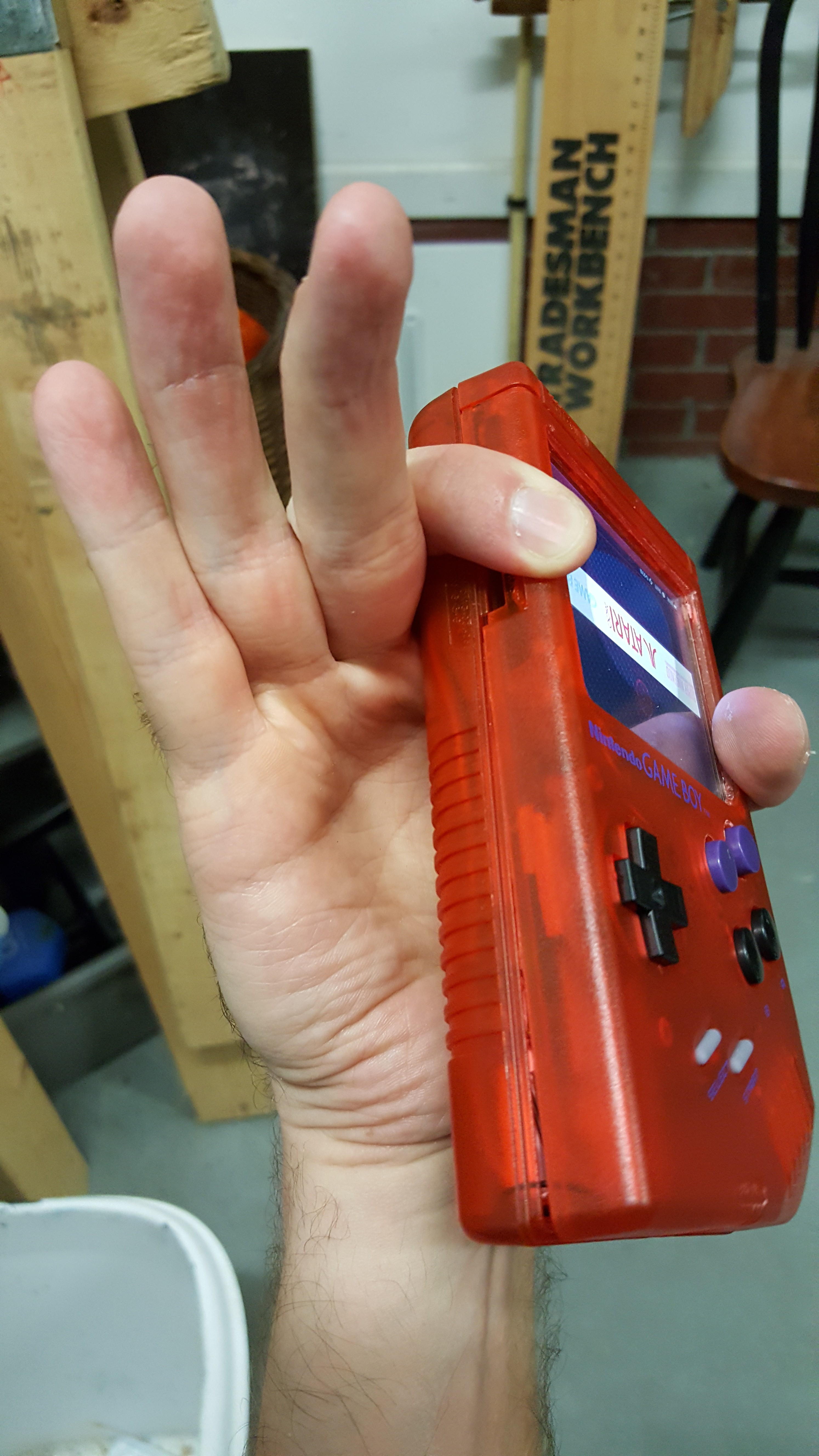
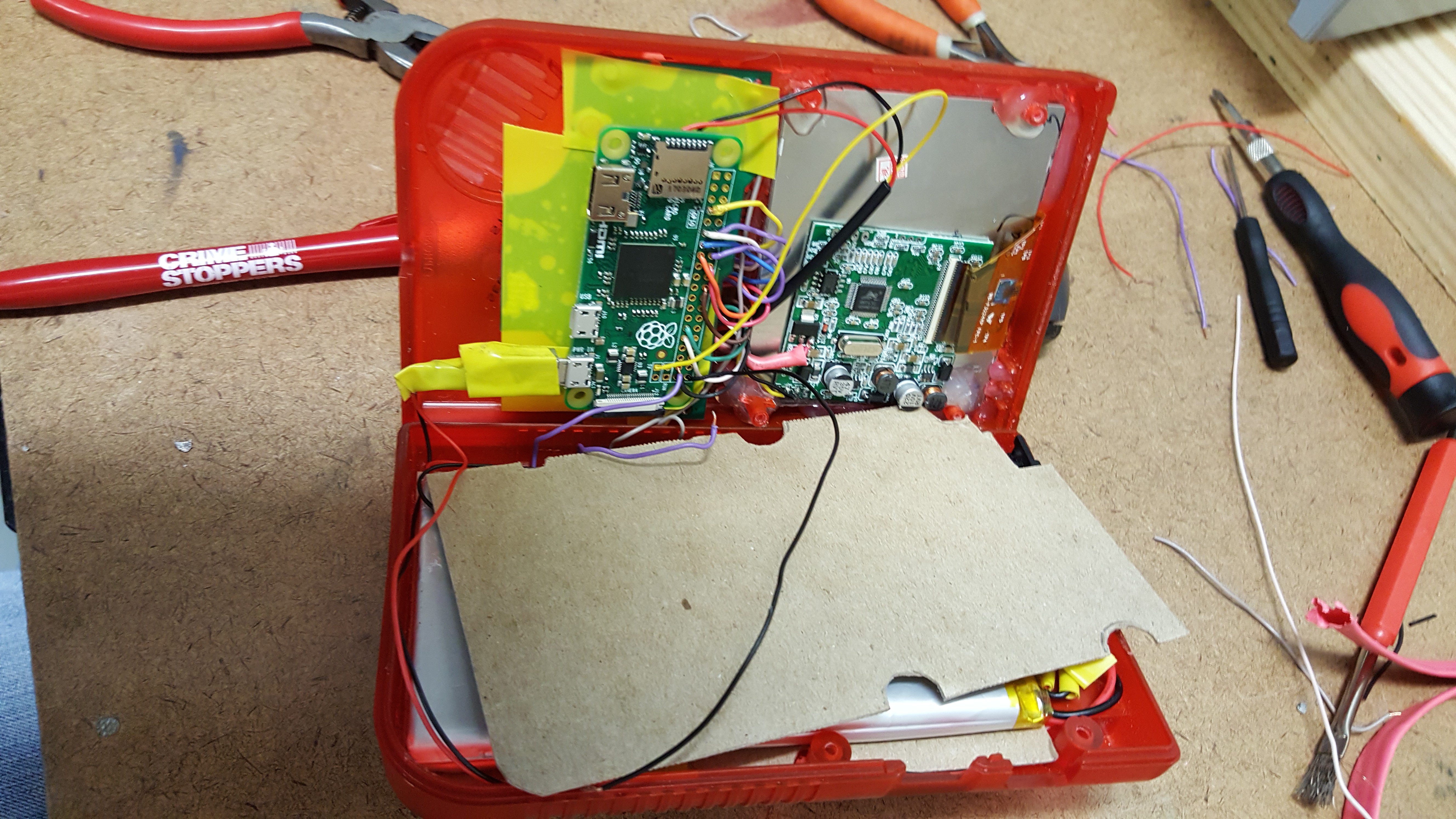
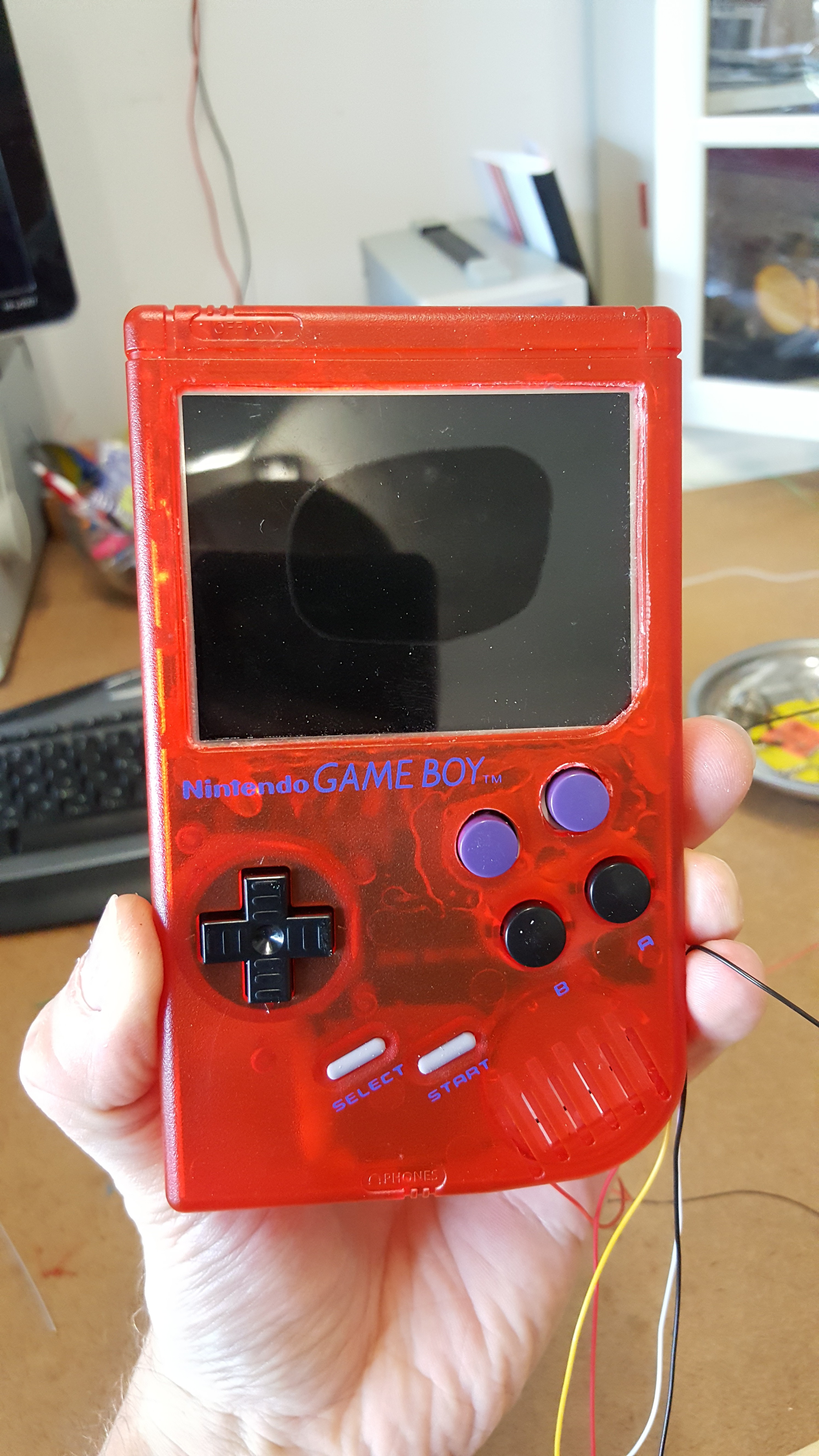
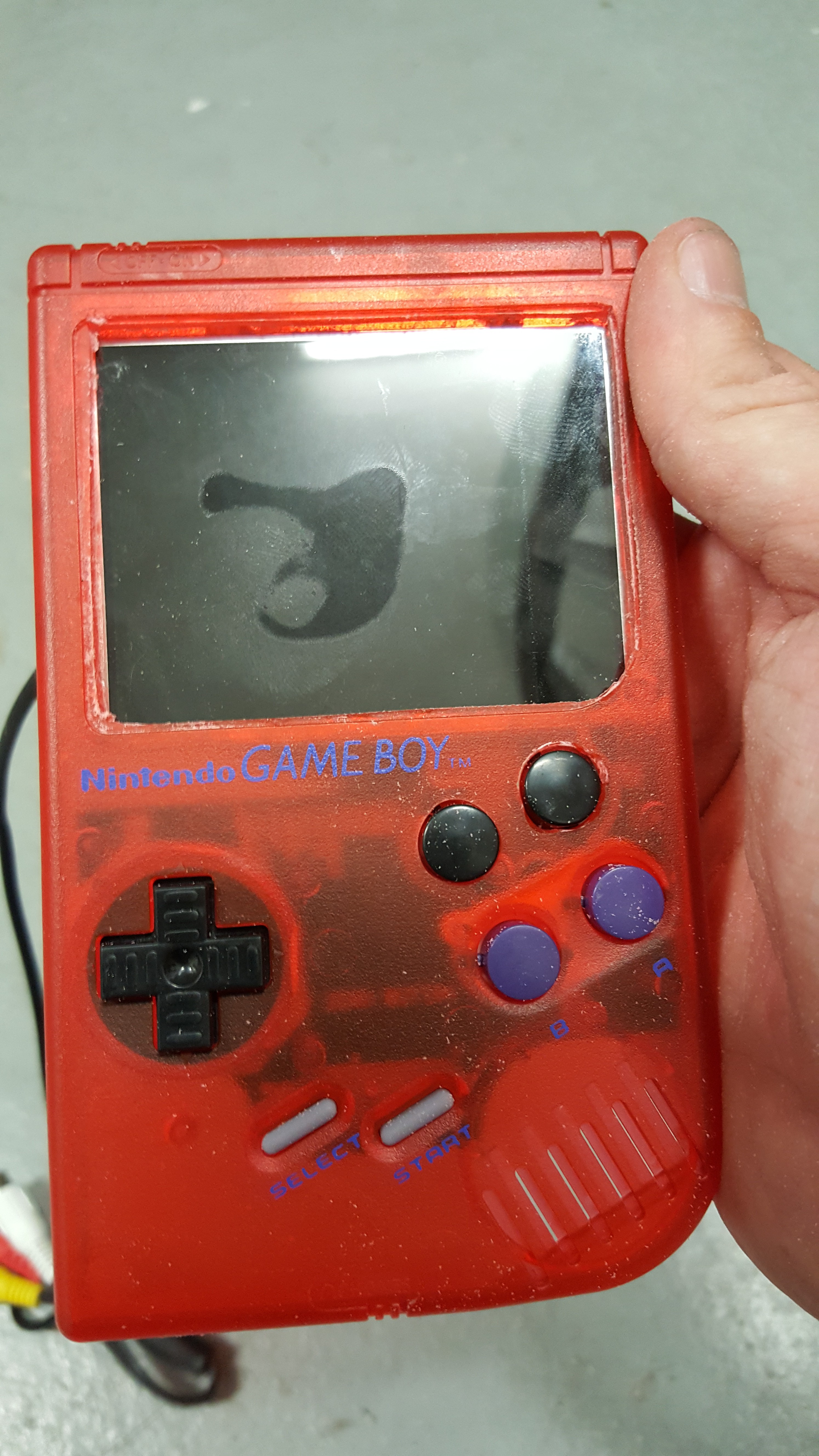
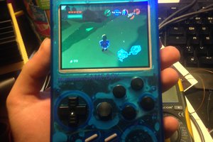
Here's some pictures from before I took it all back apart to fix the issues outlined above. This was without screws, and the screen is upside down again because the config file dropped, and lost the line I added to flip the screen. The foam from earlier has been replaced with cardboard from an engineering pad for a more distributed insulator and base.
Okay, so I officially switched to a Pi zero. Lots of reasons but the main one is with the gigantor battery, there isn't enough room for a pi 3. I maybe could de-solder the majority of the parts and fit it that way but for 40 dollars, I'd rather not have to buy a new one. A Pi zero however is about 15 bucks once you factor in shipping. Dropping the ability to do N64 and probably the PS1 as well, but it runs everything else before that all right. For a portable, that's pretty cool. Got a lot of work done today and last night. We got case mods, basic parts layout, power systems, and buttons.
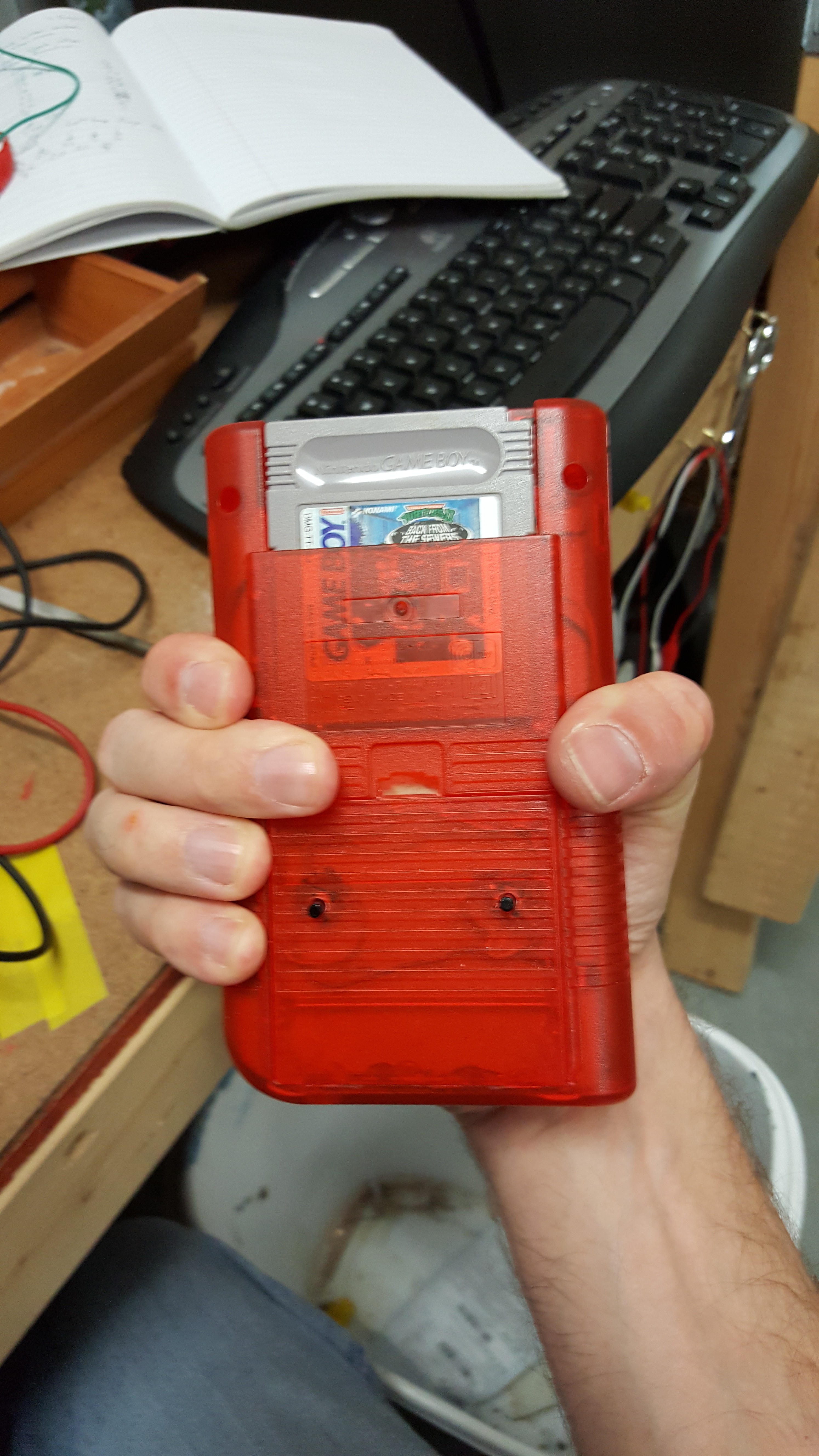
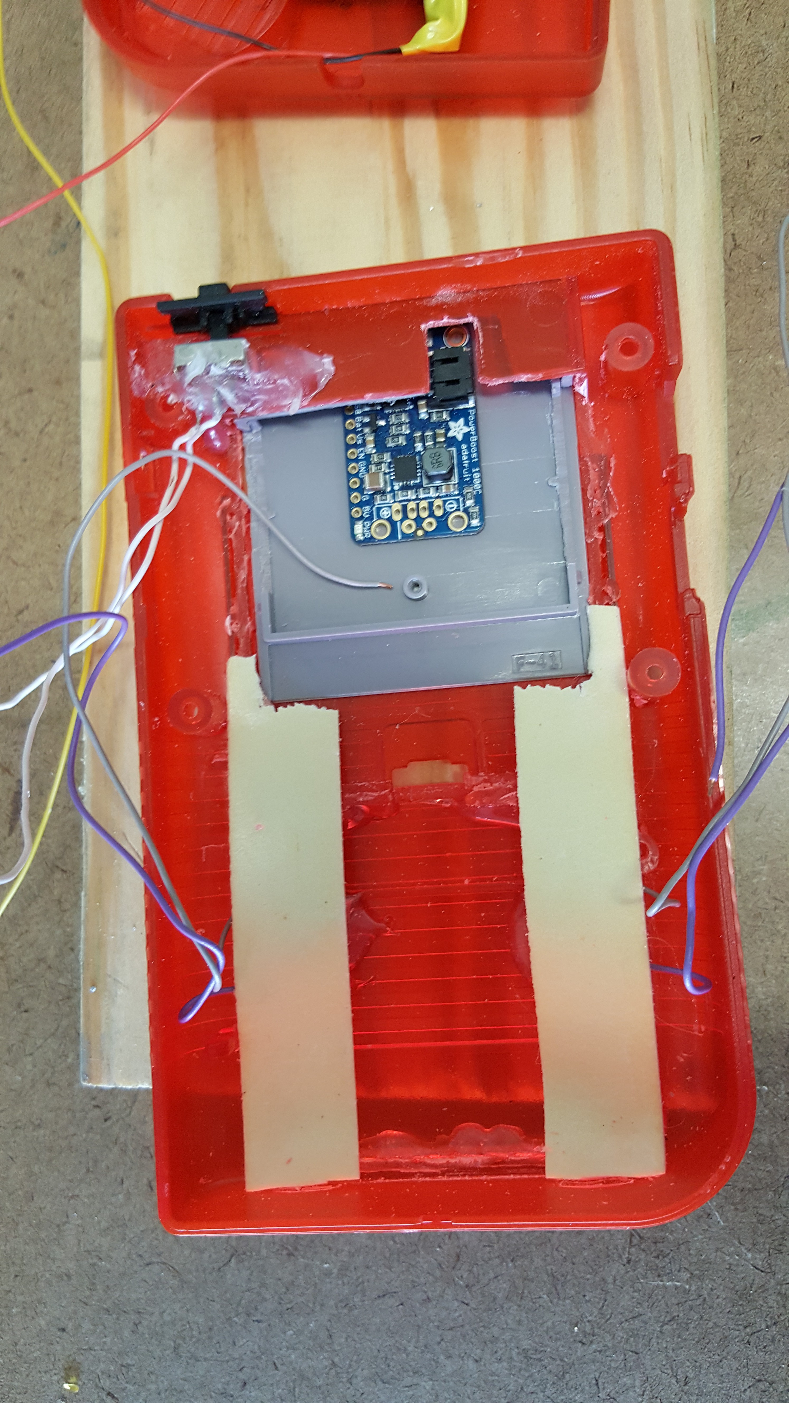
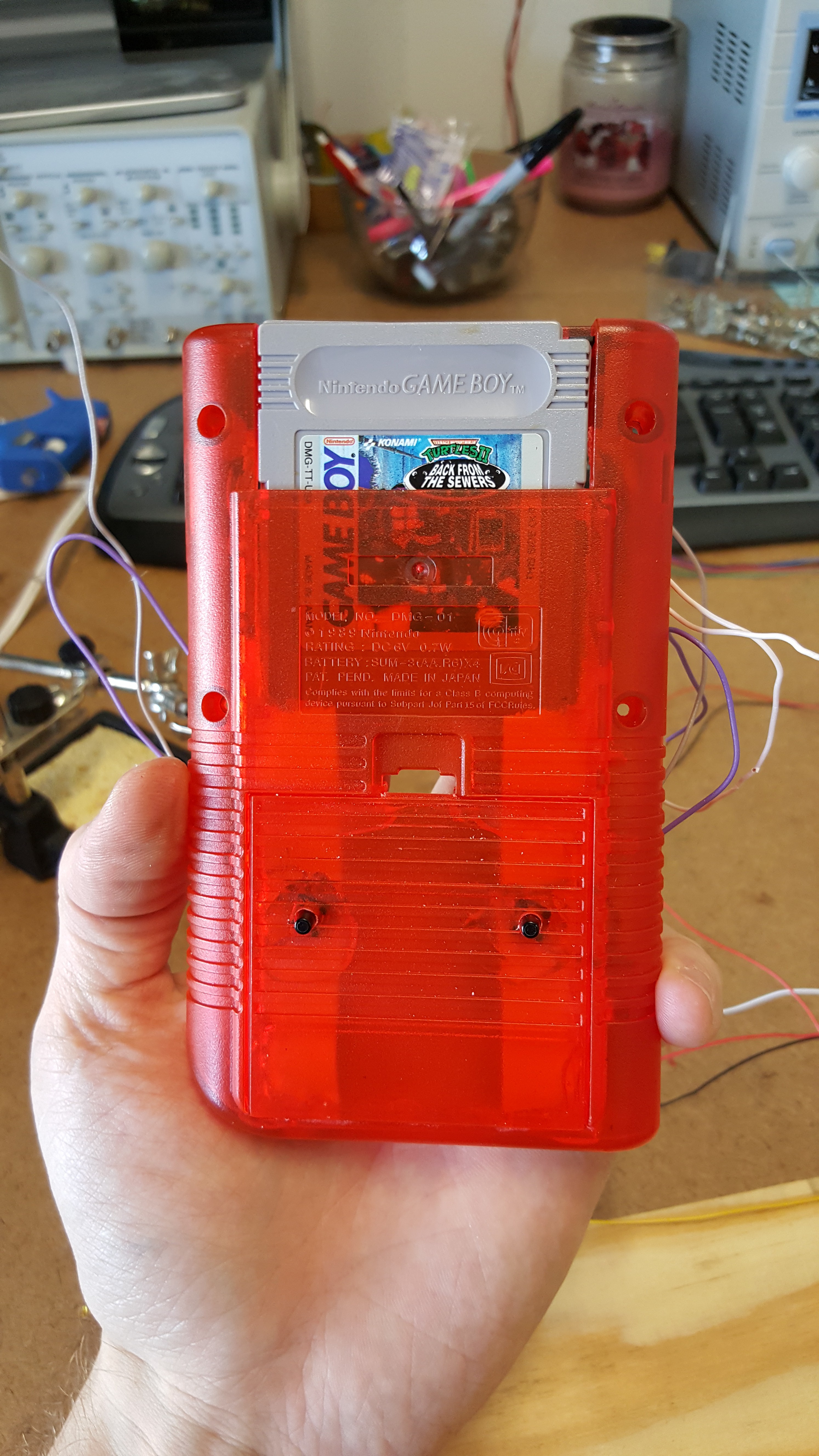
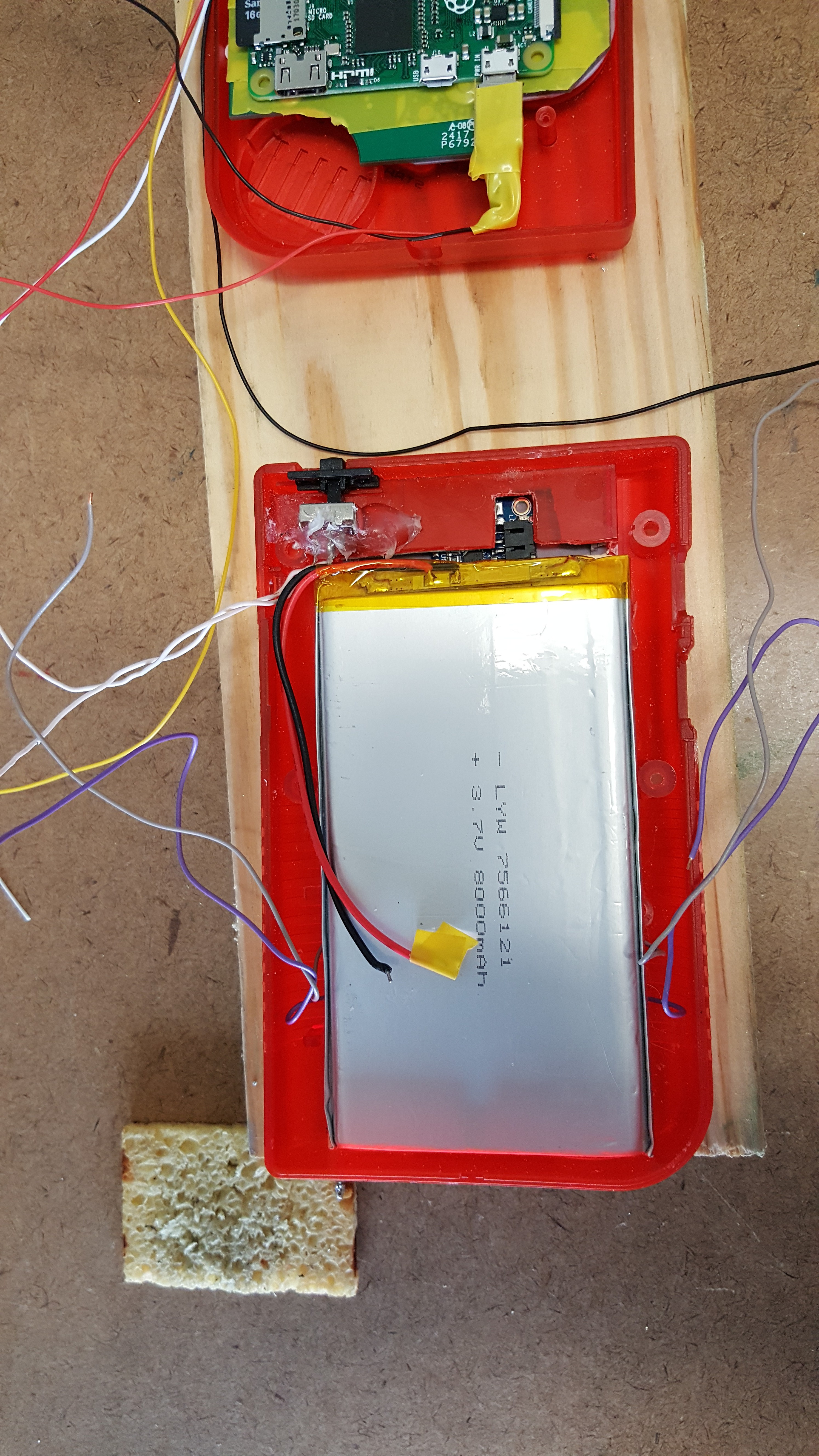
I mounted the PowerBoost 1000c inside a gameboy game from when I had a gameboy as a kid (TMNT). It probably still worked but I don't have that style of gameboy so... It gets re-purposed. The power connector to the battery (JST I think) was too thick to fit in the case normally, so the dremel and I got busy to fix that. The power switch is already glued in here, and you can see the button wires coming from behind the foam pieces to cushion the battery.
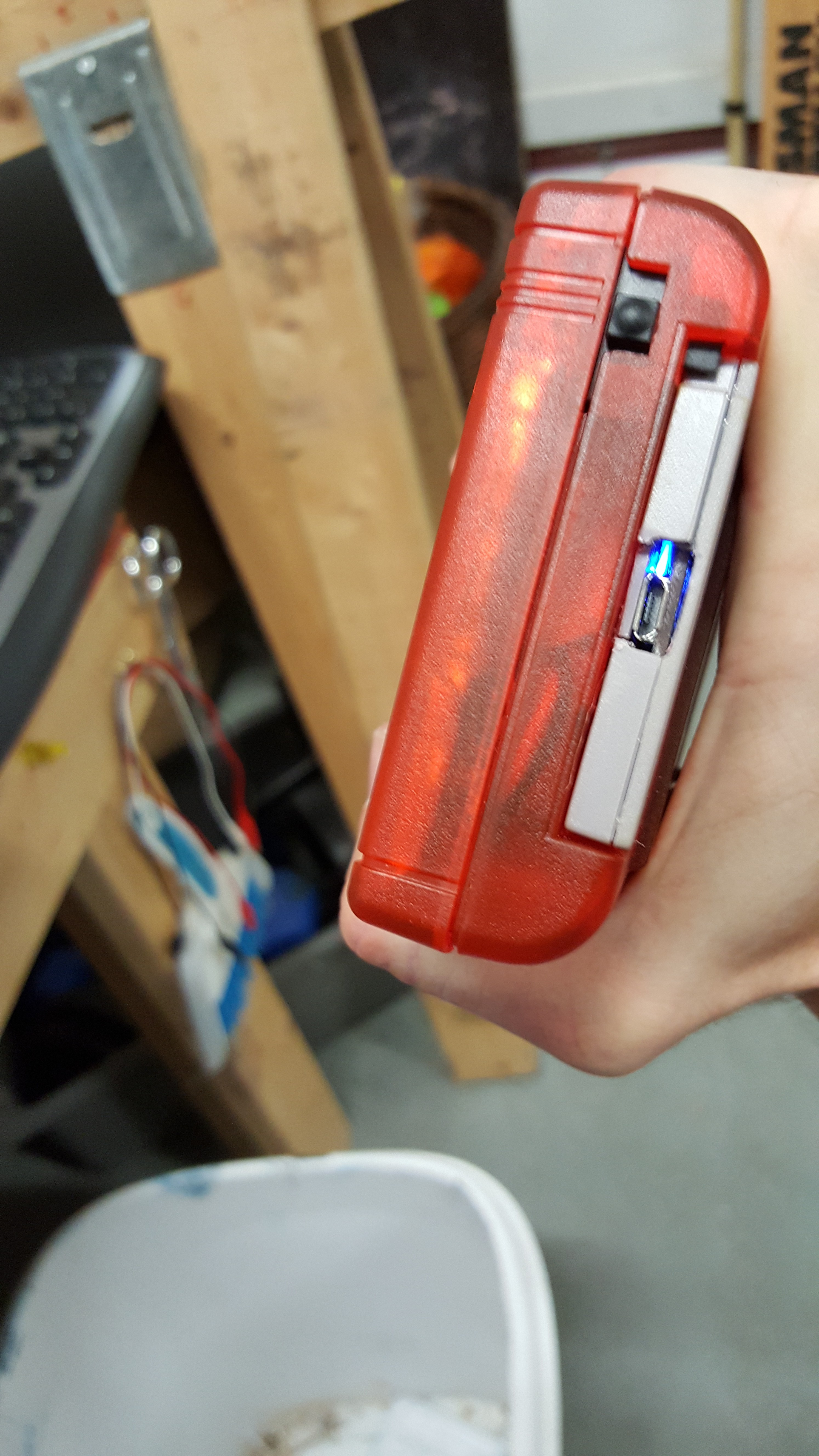
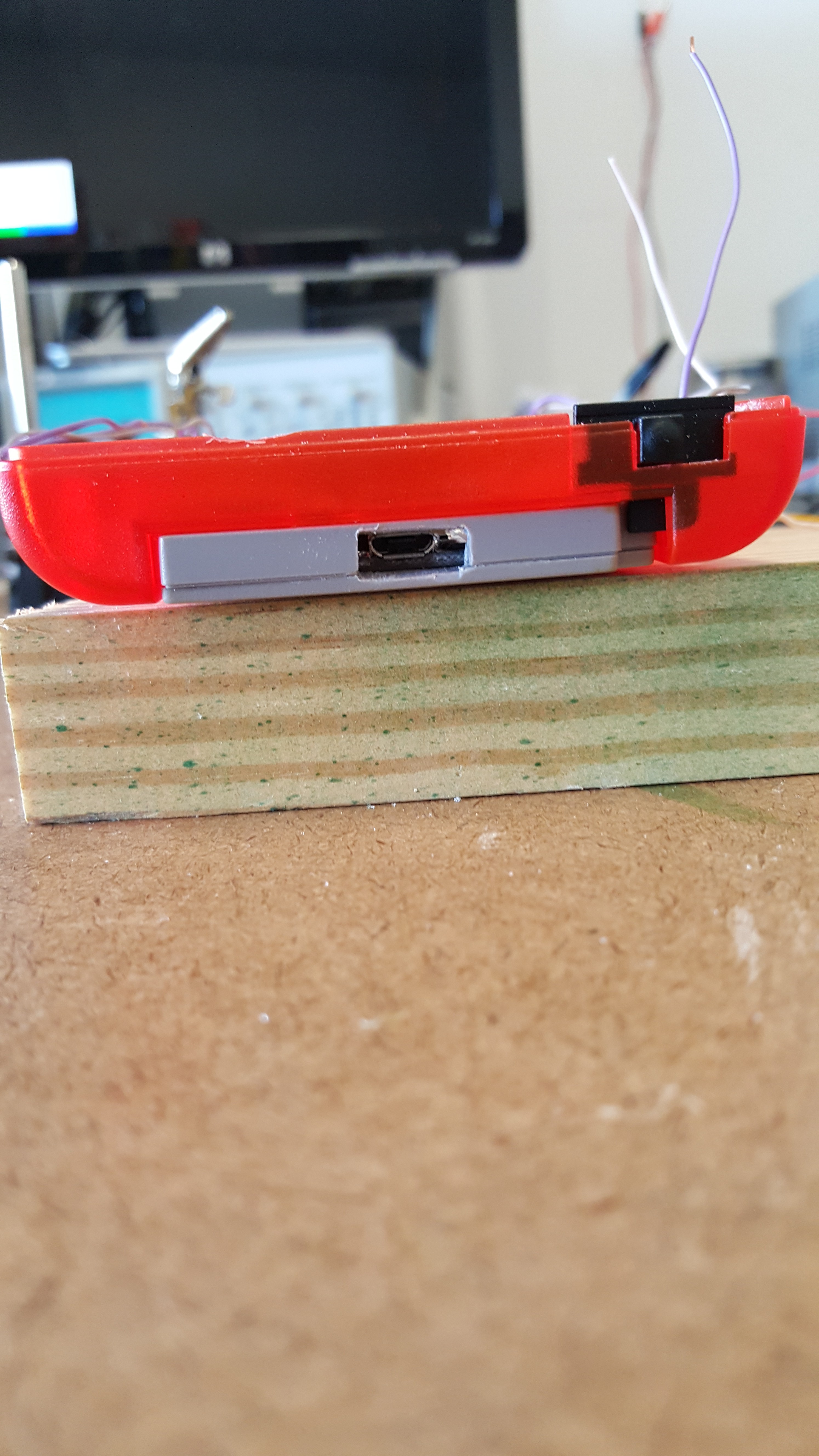
The top of it got a redo as well to make a hole for the USB charger. Not the prettiest, but better than the other placement options.
TMNT! I used to love that game. Tried playing it the other day. It was crap. Ah well. The buttons are pretty comfortable here ( I just held it normally and put the buttons where my fingers were) and if I don't need them they make a nice finger grip.
Put the start select buttons back in. (those are the video power and data cables.)
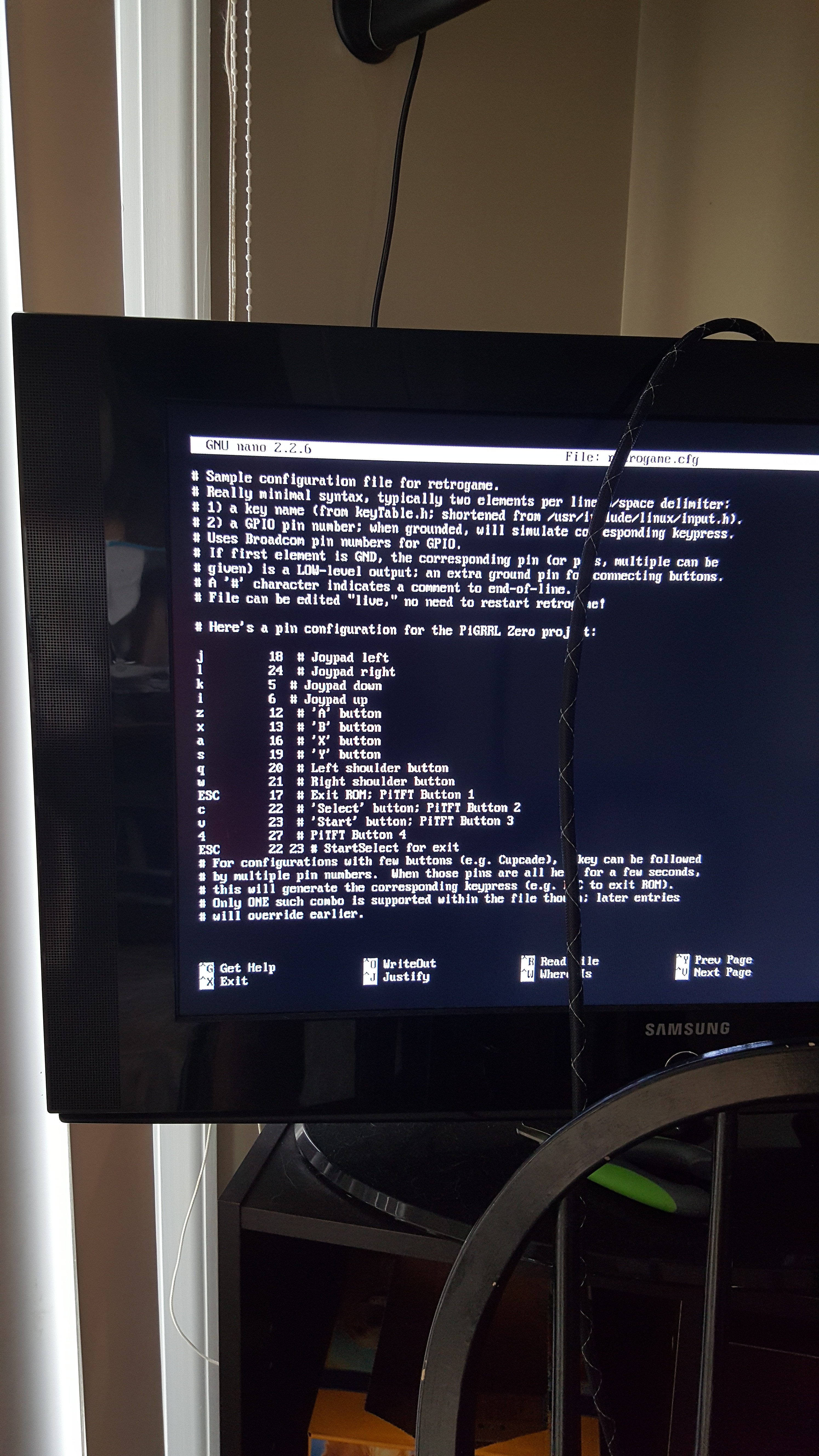
I used retrogame to program the button controller, here's the config file.
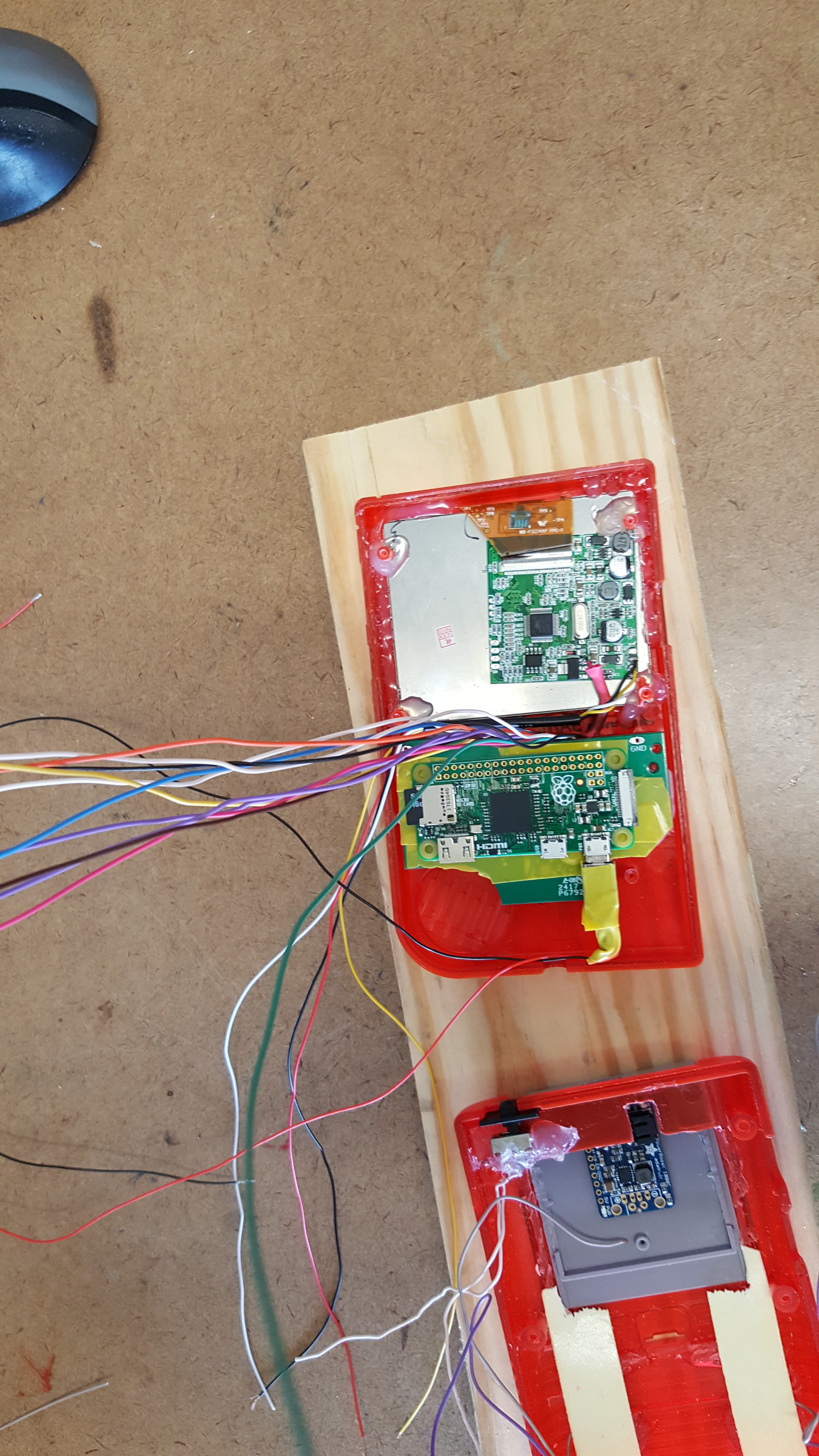
The guts (mostly) laid out where they'll go. The audio amp will go in the bottom right below the controller board, and the speaker will go in that speaker hole. There's enough depth in the case that even with the battery installed, everything still fits.
That's about all for today. I can really see how this is gonna feel as a finished product, and it's coming along nicely.
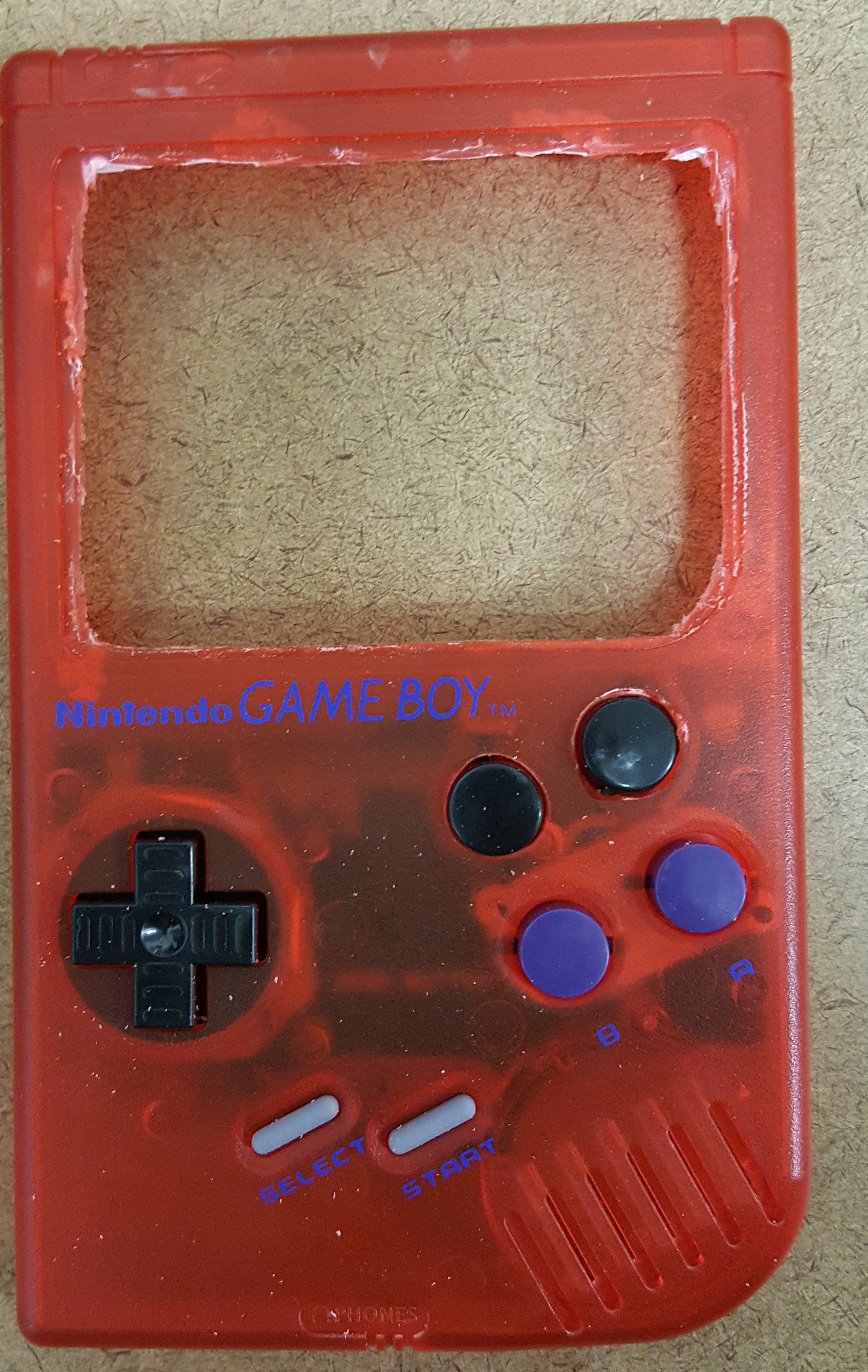
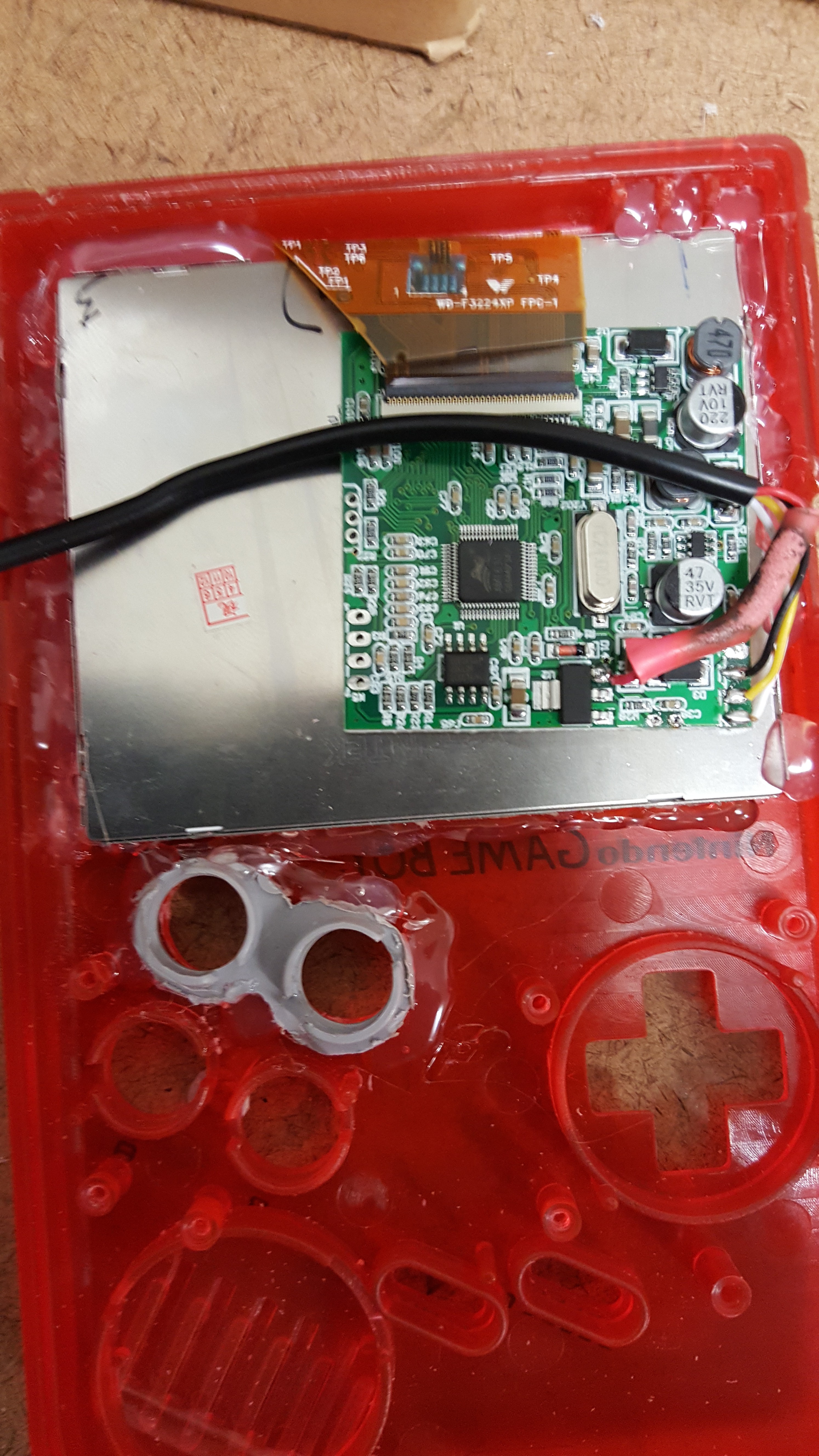
Parts are here! Got the Pi zero loaded up and tested for basic Retropie software and a few roms to make sure it works. Man, this thing is tiny after working with the larger Pi 1 and Pi 3 models. Began modifying the front case. Initial holes were drilled for the x and y buttons using a jig that came with the controller board. Used gradually larger drill bits to widen the hole, and all went well until the last part of the second hole. The drill bit seized up on the case and whipped it out of my hand and started it spinning. Put a wider gouge on one side of the y hole than is needed. Not super bad, but I still notice it. A dremel with a round flat disk cutter blade thing was used to do basic cutouts for the larger screen while keeping about 2 mm away from the edge I wanted to keep.
After that a large flat file was used to clean up the holes.
Next I checked the fit of the controller board with the new button holes and the monitor. I'm just holding them in place for this, I haven't glued or screwed anything yet.
I cleaned it up from the shavings after this. The monitor was glued in place and the connecting cable clipped down for easier handling. The upper buttons were very loose originally as well. This would not work for any kind of gaming using the top buttons, so I switched the black ones up to the top because they were larger slightly than the ones harvested from the SNES controller. The buttons spun and wiggled entirely too much. In the casing for a SNES controller there are the same style button holders as there are in the original gameboy case. I used a dremel to cut out a double set of button holders and glued them into the gameboy case.
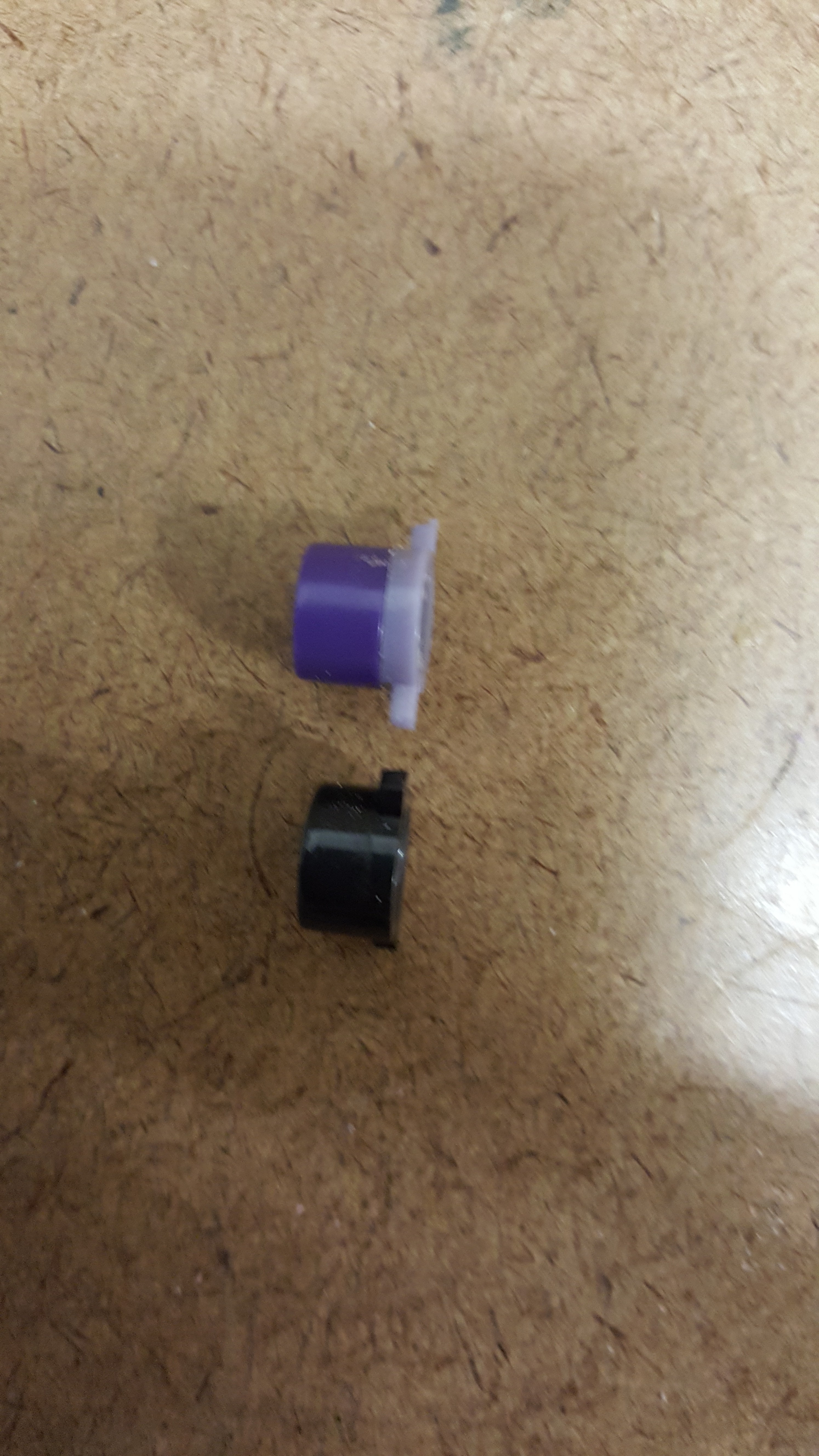
This holds the buttons very nicely in place, and I moved the purple buttons back up above the black ones. Now the problem was the added depth of the button holder made it so that the buttons didn't stick out far enough. Using a file and a screwdriver to stick in the button I filed down a lighter purple button, and filed off the tabs on the darker purple buttons. I glued the filed down button to the back of the darker purple button. This worked much better. You can see the approximate depth needed versus the black buttons here.
After this I wanted to give the glue some time to set firmly in place, so that's all for right now.
Parts will get here in the first couple of weeks of September, waiting to see how the Pi 3 runs off the 1000c power boost before I change the project over to a Pi Zero. It's already on order but I really wanted the ability to do N64 and PS1, so I'm holding out until it gets here.
Classes started back up and it's been a hell of a week. Bout had a panic attack over learning differential equations from a speed teacher. Wound up dropping that course, will take it next semester with a different teacher. It's all about matching your learning styles people.
Anyways, after taking a long look at the amperage this Pi 3 is going to need I've decided to scale it back a bit. Gonna drop back to a Pi zero (which smacks of defeat) and limit the emulation up to Super Nintendo. I want this project up and running before the end of the semester. Just got a little more money on the side to pick up a 1000c booster and a zero. Going to be cheaper to order it from England and have it sent overseas then just ordering it directly from Adafruit with the shipping... probably order two of em just so I have one on hand for future projects too. The other Pi will go back to projects and desktop gaming. Still looking at the desktop variant of the Pi Boy as well, and having the wiggle room from a smaller form factor will help. Keep hoping to see a free shipping promotion for Adafruit but haven't seen any yet. The most local store that carries them is an hour away. Getting settled into the school swing again though so I will be back on this project as soon as the parts come in.
Amperage is going to make or break this project running on a 3. I was using a 3 for the higher level emulation, and with higher levels comes higher power consumption. I still need to do some more testing with the benchtop power supply to confirm, but I may be on the higher end of the scale as far as what a 1000c is able to supply. I could move the project over to a powerboost 1000, which could supply 2.5A but then I need to find a charger for the battery, and if it's in line with the powerbooster I won't be able to plug and play like a console. I'm going to do some further testing with settings and USB adapters to see how much I can actually pull in amperage running the pi 3 at close to the limit with 64 emulation and PS1 emulation. It wont be the end of the world if I need to back it down to a SNES max emulator, but I hate to compromise the function I wanted if it's possible. Main constriction now is money and purchasing power. If I could buy a 1000C and a 1000 powerbooster and a seperate lipo charger I would just do that and test out both builds. Ah well. I heard once that necessity is the mother of invention. From specs online I'm betting that the charging circuit will limit the whole shebang to 1 A max out anyways though. Adafruit doesn't intend to make a larger C class booster either. So looks like we're stuck trying to make this work.
The case came in today, I swear these things were bigger when I was a kid. Going to have to modify it a lot to fit all this fun stuff inside. The battery is much larger than anticipated, and will probably dictate the majority of how things are lined up. The HDMI ability may wind up a pipe dream. No where near time to call it yet though. Haven't even drilled out the battery pack yet so there's loads of space to free up yet. Right now I'm test fitting the things that HAVE to go in a certain place. Monitor and control board both have to be in one spot. Found online the test pads I need to power the Pi, I'll hook up everything and see what effects killing peripherals and wireless has on power consumption as well.
So... I feel dumb. I was overly worried about making it so that a power source could be plugged in without the battery also supplying power... I realized earlier that the battery is in line with the power source because duh how else are you going to charge the battery... So that was a waste of thinking... So this simplifies the plug in console idea considerably and I don't need to imagine kill switches that force the battery to be disconnected before a power source can be plugged in... I'll just see myself out. Now I just need to desolder the double USB ports and replace it with a lovely single USB wired to where I need it for positioning and figure out the HDMI port.
HDMI takes precedence because I really don't want to try desoldering that... yeah. A quick google search later and I'm convinced. 19 freaking data lines, smushed really close together... I'll leave that alone. I was micro-miniature repair certified once, but there is no way in hell I'm going to risk it on a part I own until I am a little more financially able to replace said 40 dollar board. USB is much nicer, 4 to 8 connections with enough room to work with. I believe the power converter even came with a single USB female port, which I could wire around to wherever I have enough space.
Really need the case to get in so I can put in the pieces that MUST go in a certain spot like the monitor, HDMI port, and controller board so I can see where I can fit in the battery, audio amp, power booster, charger, volume knob, etc. Glad it's a DMG gameboy, should have plenty of room to work with once I remove excess plastics for battery compartment and unused posts.
Before I sank too much extra into this project I just ordered enough to get a small prototype working alongside parts I already have. Now for the downside of being broke: waiting in the middle of a project for the rest of the parts to arrive. We have on order the battery, shell, tiny speaker, rainbow ribbon cable, and a prototype board for next time. The battery we went with an 8000 mAh offbrand because it was 2000 mAh more for about half the price. Gonna check it reasonably well before it gets plugged in though. The ribbon cable is a rainbow color because I have bs ptsd from counting all those ribbon cables on the flat grey IDE cable, also because it will look pretty under the transparent shell. (It's a see through red one.) The speakers are from an GBA, and were two for like 80 cent. I am ok with that. As funny as this huge speaker is, I don't really care to try to fit things around it in the DMG shell. The shell should be here in about a week or so, but the battery is right here in NC, so I'm hoping it gets here fast, and I have enough time to test and wire it into the recharge and step up circuits. School starts back up next week too, so hopefully I can finish the majority of this project before things get hectic again. Looking forward to having this on campus for the days when I have a long stretch between classes. This will probably be the last entry until the battery gets in. I may use the time to back post the test tube project.
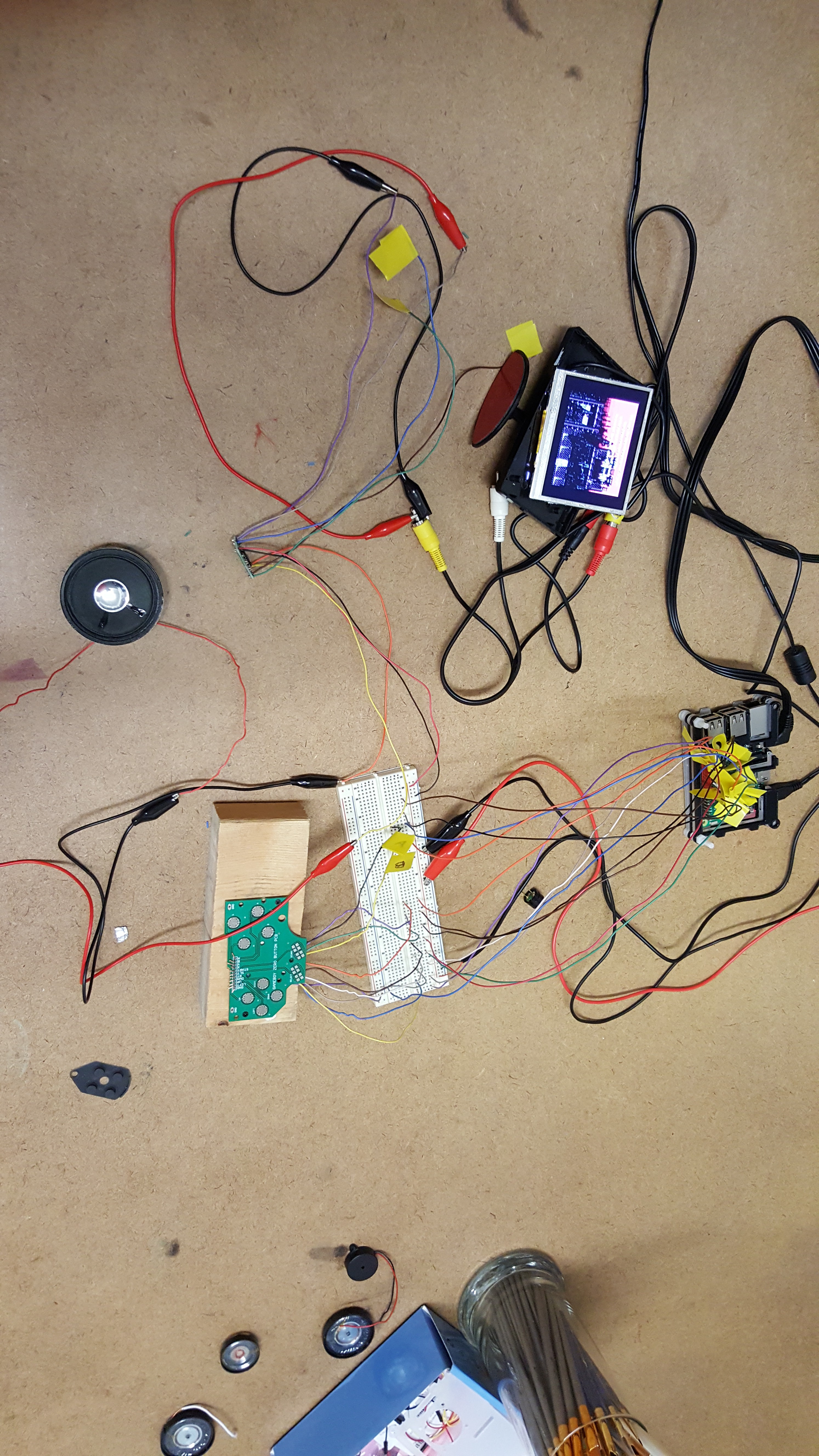
Wanted to do a functionality test, so after soldering the audio amp lines in and finding a speaker that would work for this, I hooked everything up and IT WORKS! We have controls, video, sound, and emulation people! The sound is a little on the quiet side, which again I thought could be resistance in the breadboard, but it persisted even after bypassing it. I'll look into audio improvements tomorrow if there's time, but in the meantime, we have working guts! Minus the Pi, I am seeing about a 375 mA draw on average, so depending on the pi requirements, we're looking at around 3 hours battery life on a conservative estimate.
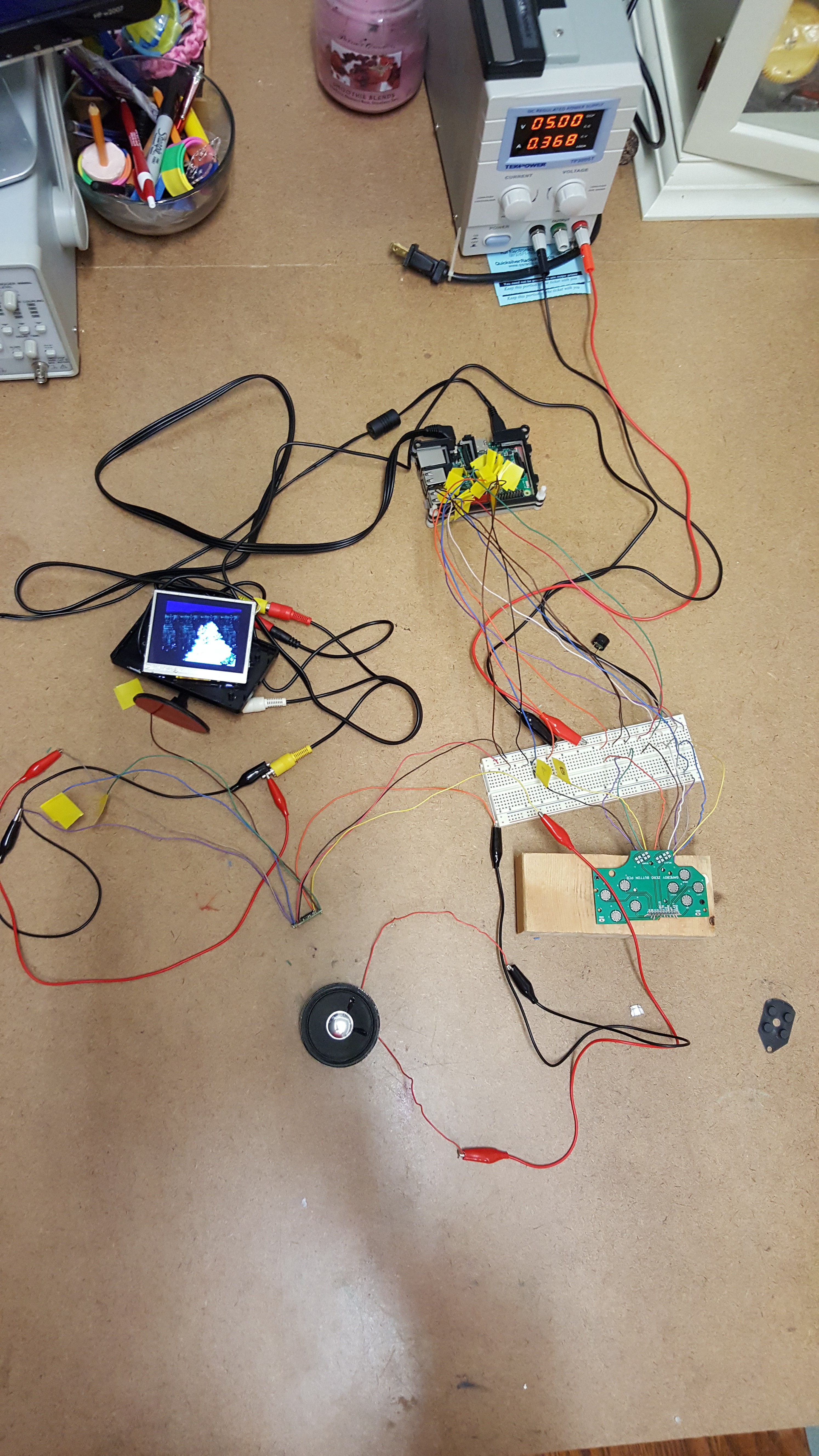
Now to order the battery and case for fit tests. The power circuit I can't do with out the battery because the battery will directly feed everything, even when charging.
 sotasystems
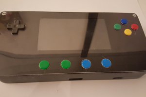
 Lumor
Lumor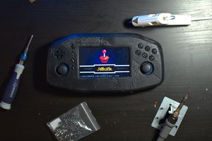
 Brandon
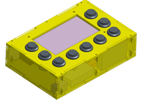
 Craig Hissett