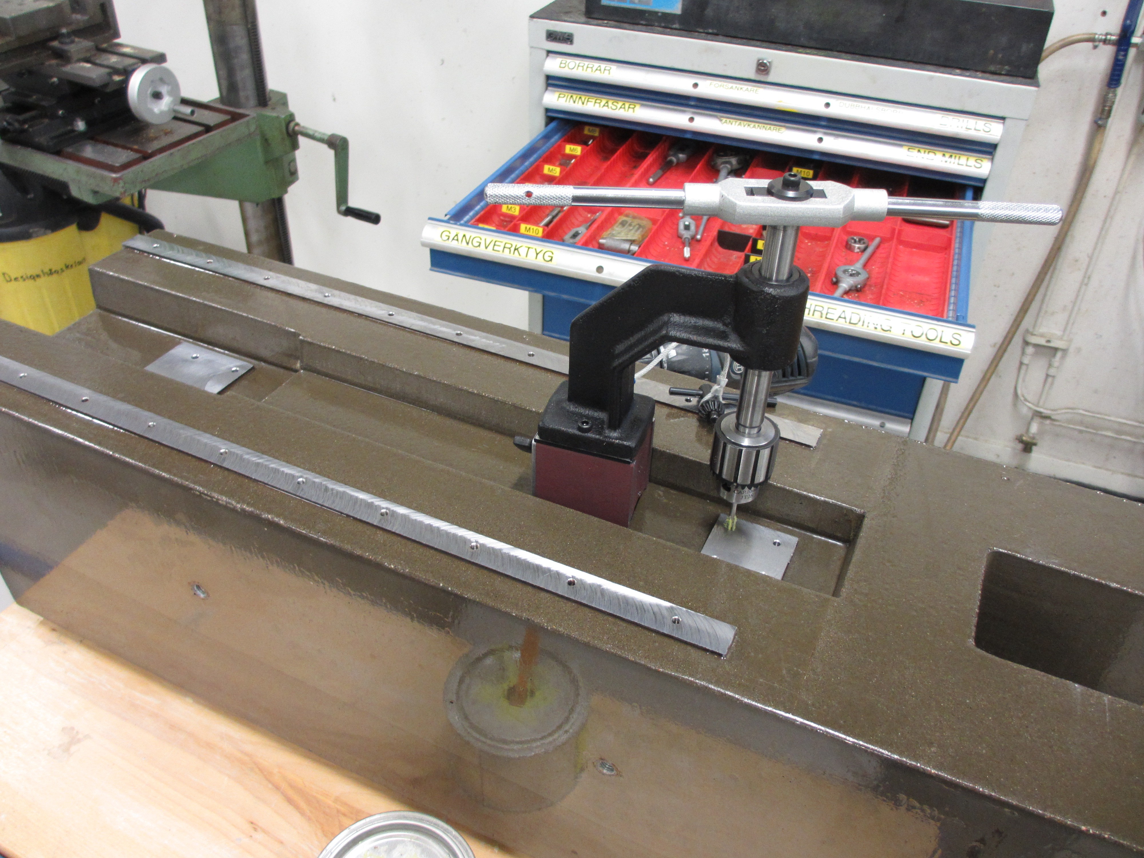
Time to work on the steel inserts. First step is to get the tower onto the milling machine and checking how flat the rail mounts are. I found them to be within 0,4 mm out of plane, and since they are sticking out 4 mm from the concrete that translates into no problem! Since the purpose of this next step is to mill them perfectly flat (and also drill some holes for the ball screw mounts). After also making sure the block is aligned with the X- axis of the milling machine, I clamped the block down and set up two extra dial gauges between the table of the block so I can be sure that it is not moving during machining. 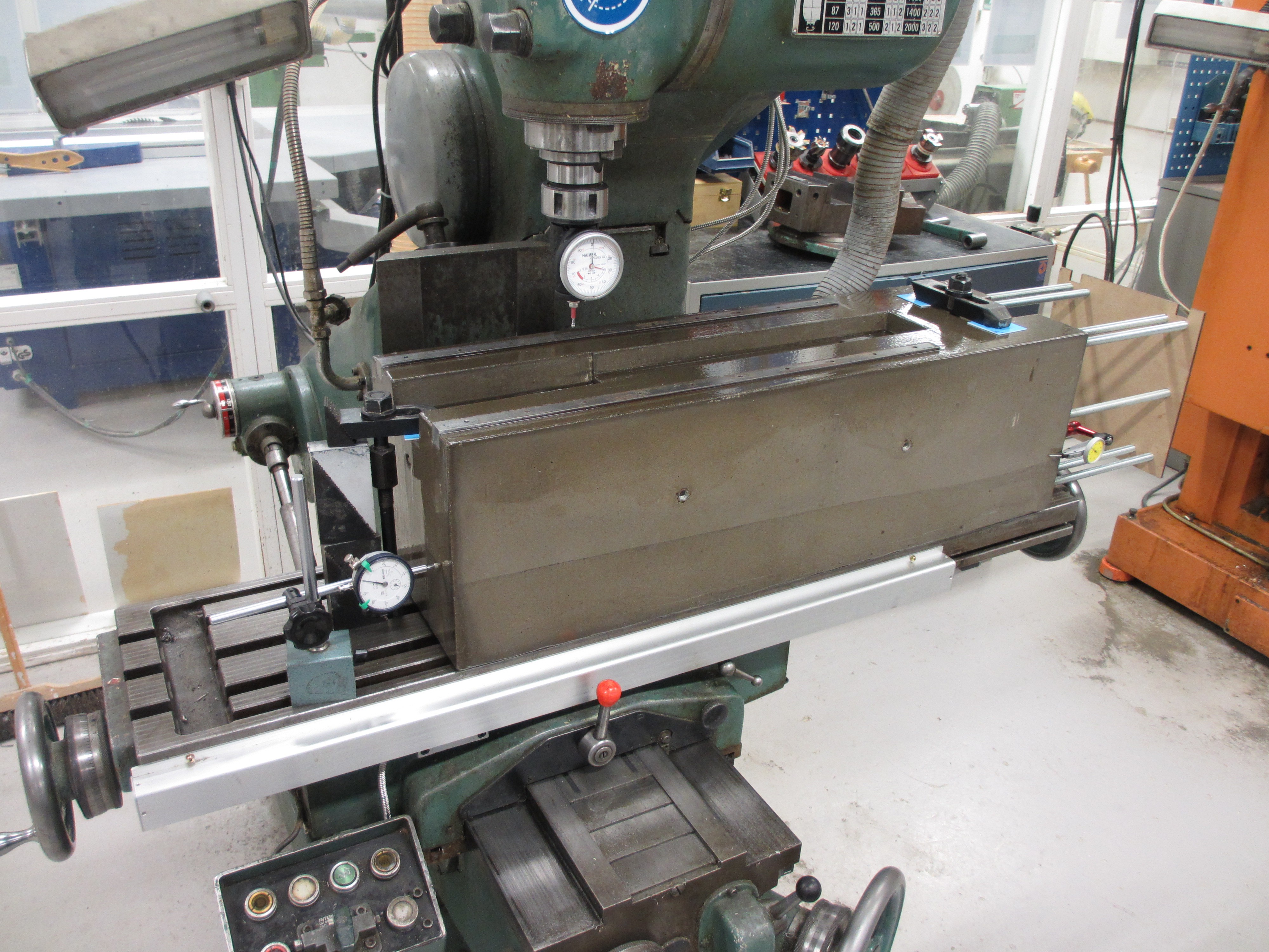 To avoid twisting or bending the tower while clamping, and thus loosing precision, it is clamped down on three small plastic feet. Having only three points of contact, and placing the clamps right above the supports, prevents the tower from warping under the clamping force.
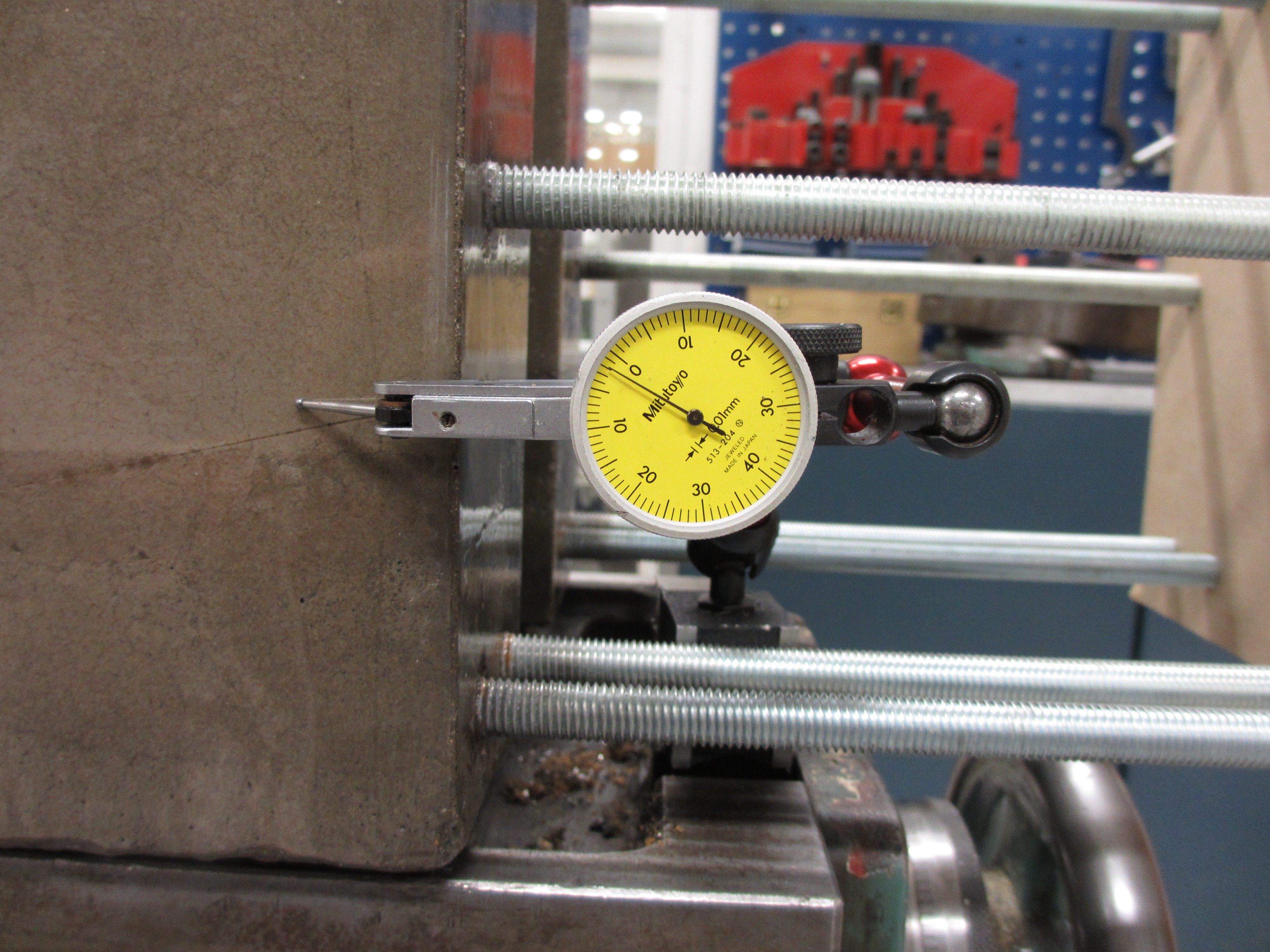
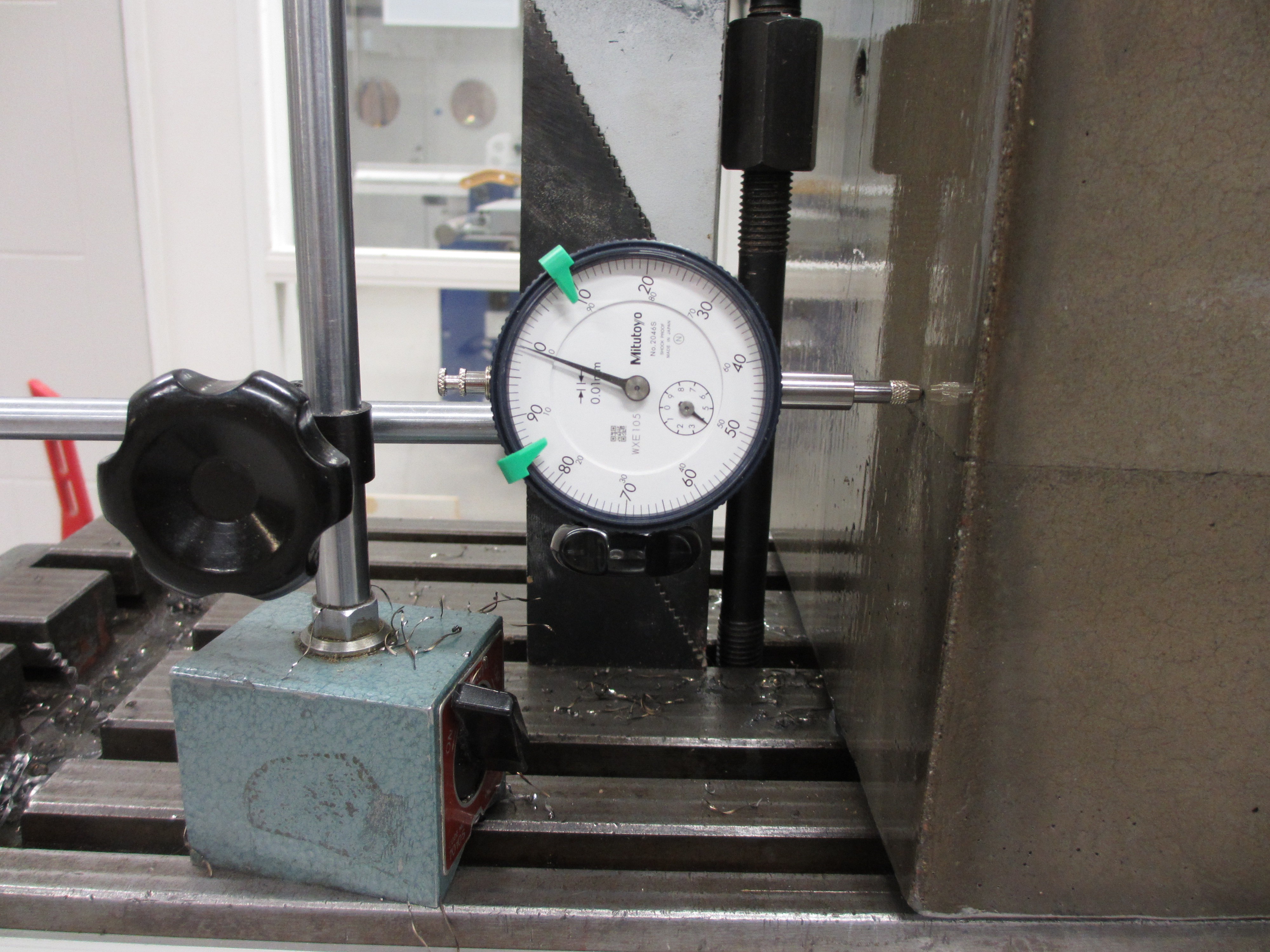
  During machining, the block did move a bit. But only 0,01 mm in X and 0,02 mm in Y.
Such a small imprecision is not an issue, since the X and Y zero points were only used for drilling holes for the ball screw mounts. These will be tapped and are quite forgiving. A bigger problem is that due to the weight of the concrete, I concluded that the machine table was actually flexing slightly near the ends of X-travel. I estimate it may have flexed some 0.015-0.03 mm. This will probably cause the machined surface to "arc" a bit, having a high spot in the center. I'll have to verify the results and see if they are good enough.
 And this is what it looks like!
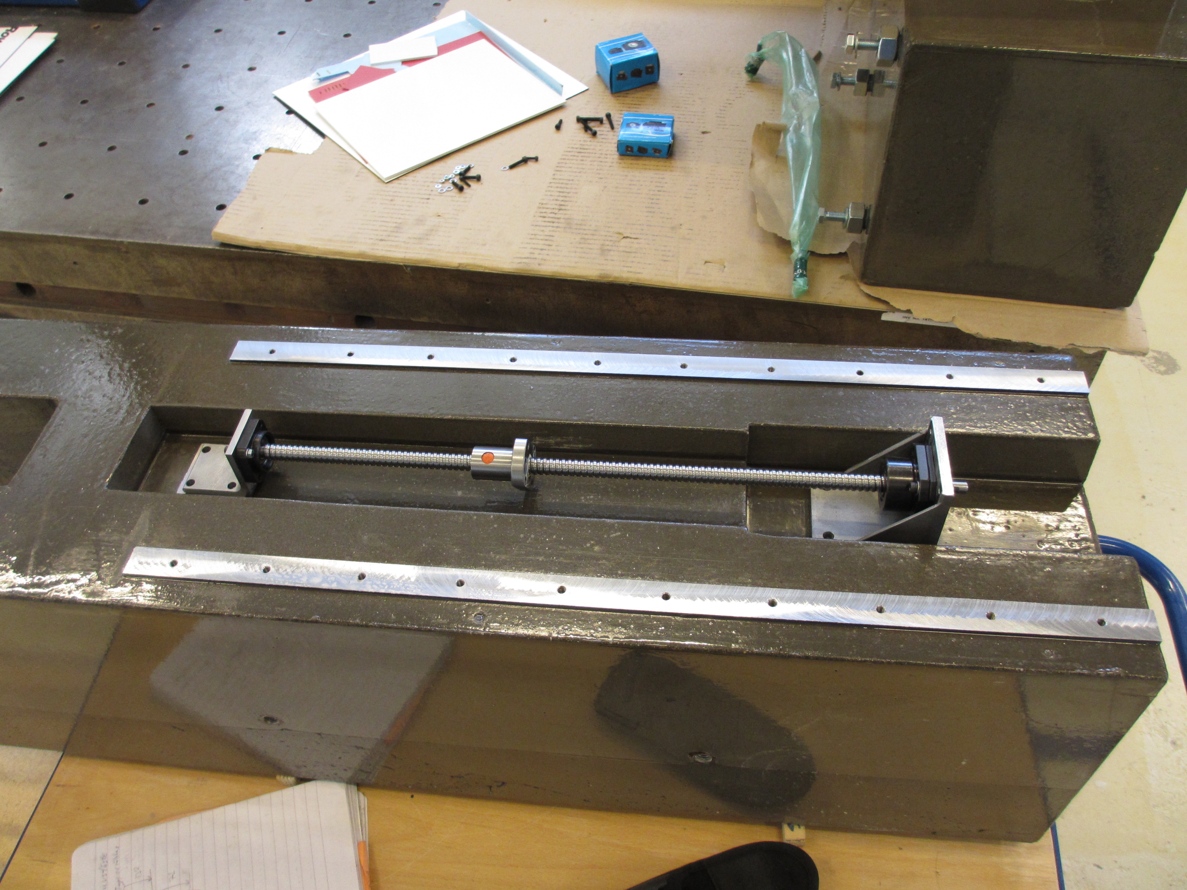 Next up is measuring the flatness of the rail mounts and mounting the rails.
Discussions
Become a Hackaday.io Member
Create an account to leave a comment. Already have an account? Log In.