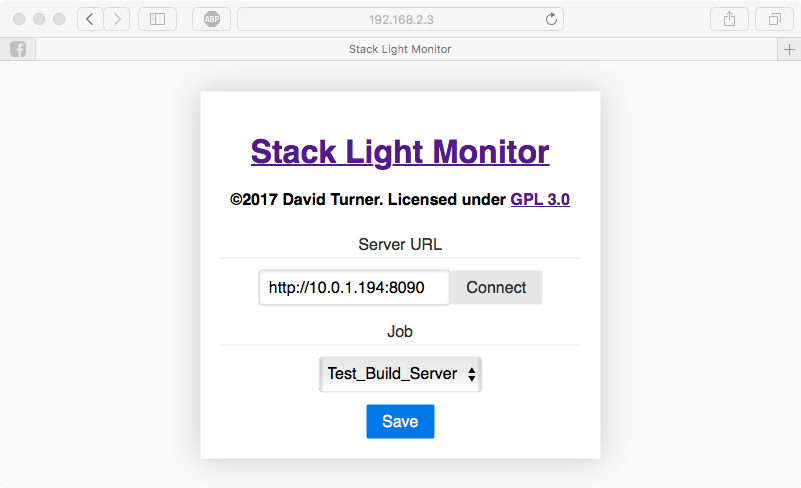
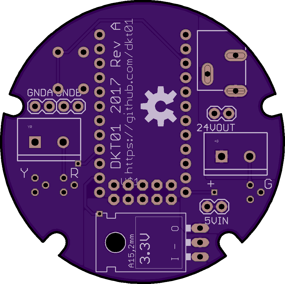
Close
0%
0%

Stack Light Monitor

Jenkins build monitor using an industrial stack light as output.

Similar projects worth following
Because my team at work recently moved to a new location and we no longer have a visible spot for our Jenkins build monitor screen, I wanted to make a simple visual indicator of our project's build status. I made a tree monitor last year, but it claimed a static IP (so it couldn't be connected directly to the work network) and it required a computer actually query the Jenkins status and parse the responses. Plus, the holiday theme only really works a few months of the year.
This iteration uses a 24V industrial stack light I found on eBay along with an Arduino Pro Micro and an ENC28J60 ethernet adapter to directly monitor a job on a Jenkins server. The Arduino hosts a web server for a configuration page and accepts new configurations via a RESTful API. It uses the Ethercard library to acquire a DHCP address on the network, perform DNS lookups, and send HTTP queries to the configured Jenkins server. The Arduino software parses the JSON responses from Jenkins to set color
  • 1 × Arduino Pro Micro 5V/16MHz I used a clone I found on Amazon
  • 1 × ENC28J60 Ethernet LAN Module To fit in the enclosure, use the Gikfun Mini form factor
  • 1 × PATLITE LES-AW 50mm 24V Stack Light
  • 1 × 24V DC Power Supply with 5.5x2.1mm Jack
  • 1 × eBoot Mini MP1584EN DC-DC Buck Converter Adjustable Power Step Down Module Any 24V to 5V converter should work

View all 14 components

  • Demo Video

    dkt0108/28/2017 at 03:41 0 comments

    Here's a demo of the stack light monitor in action!

  • Web Config

    dkt0108/27/2017 at 21:21 0 comments

    Let me be the first to say that the Arduino makes a pretty bad web server.  With only 32KB flash (<28KB available for program memory) and only 2.5KB RAM, there's not much room to store or serve anything.  Thankfully, the ENC28J60 can handle a lot of the lower-level stuff and the Ethercard library from [jcw] has some good abstractions for TCP connections.  I ended up writing the website as a single file HTML/CSS/JS page that I then minified, GZIP compressed, and converted into a program memory character array in a header file.  This enabled the whole webpage to be static and stored in program flash saving valuable ram for other tasks.  Since I had a little extra room, I used the Pure css framework to make the site pretty.  Oh, and I also made a compressed favicon.ico so everything looks a little more professional.

    The webpage itself uses pure Javascript to find jobs available on a server and validate settings before sending everything to the Arduino.

    The Arduino uses a RESTful API to interact with the config page.  The webpage uses a GET request to retrieve the current configuration of the Arduino, then it uses a PUT request to save new settings.  The Arduino does some internal validation before saving settings in EEPROM and sending a http response code to the web page.

    The Arduino uses these configuration settings to send HTTP API requests to the Jenkins server.  It then parses the JSON returned by the server to set the light pattern.

    TL;DR: The Arduino is acting as an HTTP server and HTTP client simultaneously in under 28KB flash and under 2.5K ROM

  • CAD

    dkt0108/27/2017 at 21:02 0 comments

    As a software engineer, CADing the stand was a learning experience.  I'd done some modeling of existing objects before, but creating something in the computer first was interesting.  It was especiallly challenging to identify and rectify the interferences between the PCB and the CAD model, but my rough assembly (available on GitHub) was a good predictor of the physical assembly.

    I did everything in Autodesk Inventor because that's what I had some experience with.

  • PCB

    dkt0108/27/2017 at 20:56 0 comments

    I don't want a rectangular base for my round light, so I've decided to design a round PCB this time.  Thankfully, OSHPark doesn't care about the shape.  I was a little concerned about the rounded-rectangle shaped plated holes for the barrel jack, but it turned out perfectly.  I made a couple mistakes on the silkscreen by keeping a label that was supposed to be hidden and swapping the "-" and "I" labels for the regulator.  Otherwise I'm pretty happy with how it turned out.

View all 4 project logs

  • 1
    Print Enclosure

    I used a LulzBot TAZ 4 with PLA filament.  Layer height was 0.2mm and speed was moderate.  I used 2mm wall thickness and 20% infill.  Because the enclosure is pretty much a shell anyway, the wall thickness and infill can be adjusted, but definitely keep at least 1.5mm wall thickness so the machine screw threads have something to bite into.

  • 2
    Finish Enclosure

    Sand the outside of the enclosure as desired to create a more finished, smooth look.  I used up to 2000 grit sandpaper and the results were very nice.  Don't worry about the inside since it won't be visible anyway.

    Use a 2.5mm (3/32" if you don't have metric bits) drill bit to prepare the holes in the top enclosure piece for threading.  When I printed the enclosure, the holes were slightly too small to accept the M3x0.5 tap.

    Tap the holes in the top enclosure with a M3x0.5 tap.  This should be very easy since the plastic is fairly soft, so you may be able to skip this and directly screw the machine screws into the plastic.

  • 3
    Populate PCB

    Ensure Components near the screw notches are as far away as possible so there is no  interference with the enclosure.  Use hot glue if necessary to stabilize ENC28J60 module on bottom of PCB.

View all 6 instructions

Enjoy this project?

Share

Discussions

Similar Projects

Does this project spark your interest?

Become a member to follow this project and never miss any updates