Close
0%
0%

Emergency button : Reliable, Inexpensive & Design

Emergency Button for 7$ based on ESP8266 Wifi board

Similar projects worth following
One of the main problems for old age people is keeping their balance while walking. It is getting more and more difficult to move, and if they fall down it's very complicated to get back up. My family is calling my grandmother every evening to check for this kind of problem. There are some emergency buttons that can help, but you often have an expensive monthly payment for the call center. In addition, most old people don't like to wear some gray plastic technologies around their neck.

So my question is :

How to make a device cheap, reliable, easy to integrate, discret and with no monthly payment?

In most apartments today, you can easily reach 10 or 20 wifi connections. So I decided to build a wifi connected device, which make things easy to communicate with the external world. As a lot of old age people don't actually have a wifi, i decided to ask the neighbors for wifi access. Most of them were very happy to help and even asked to add their Email address to the list so they can quickly help in an emergency.

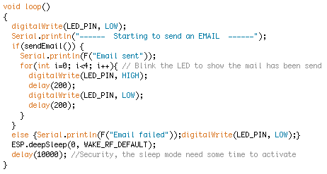
If a person is in distress for a reason, he or she has to press a simple button on the device. A LED turn on to confirm the emergency is activated. The device will connect to the internet box and send an Email to a pre-entered Email address. As a lot of people receive Email on their phone and check their phone 30 times a day (like me :s), the emergency can be quickly followed by calling the person or knocking at the door.

The device has to be easy to wear and to integrate. Therefore, it was important to reduce dramatically the size and the weight. As a result, the device is 2.5 * 1.5 * 1 cm in size ( 1*0.6*0.4 inch) which can be easily integrated to bracelets, necklaces or clothes. As some aged people are trembling a lot, the button is quite big, which makes it easier to press.

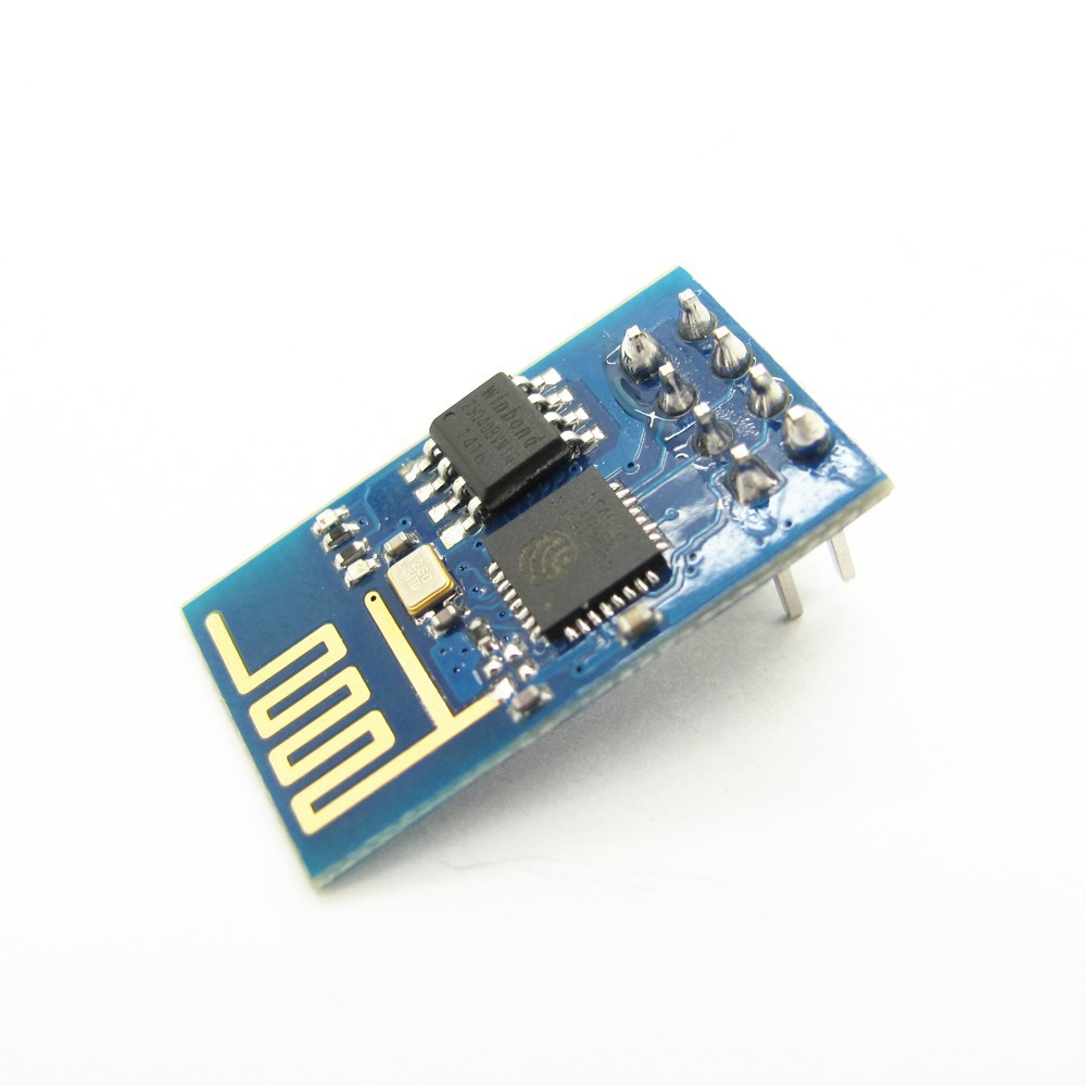
The price is also a very important question. If you want to make a wifi connected device today, the ESP8266 board is a very good choice! It costs only a few dollars and it has its own 32bit reprogrammable micro-controller (The Atmega328p on the Arduino UNO is only 8bits). A big community is now using this device and it recently became Arduino IDE compatible.

The electronic cost is around 8$ which is affordable for most people and you have to add a battery of your choice. All the components are easy to find and to adapt if you want to make a new design by yourself. A standard 110 mA battery should work more than 2 months, a CR2032 for 5 months and a 1000mA for 2 years.

Top side.STL

3D file of the TOP

Standard Tesselated Geometry - 1.97 MB - 09/04/2017 at 16:22

Download

Bottom side.STL

3D file of the Bottom

Standard Tesselated Geometry - 552.52 kB - 09/04/2017 at 16:22

Download

Button.STL

3D file. This part is to make the button bigger to be easier to access

Standard Tesselated Geometry - 24.50 kB - 09/04/2017 at 16:22

Download

Emergency_Final.zip

Final code to load on your ESP8266

Zip Archive - 1.89 kB - 09/04/2017 at 10:42

Download

Emergency_Final_Programer.zip

Final code to load on your ESP8266 and test on your home made programmer

Zip Archive - 2.01 kB - 09/04/2017 at 10:42

Download

  • 1 × ESP8266 Wifi arduino compatible board
  • 1 × Button Classic push button to wake the board up
  • 1 × LED Fiber Optics / Emitters
  • 1 × Battery Evaluation, Demonstration Kits, Boards and Modules / Evaluation Kits, Boards and Modules
  • 1 × FTDI or Arduino board To program the ESP8266

View all 6 components

View all 2 project logs

  • 1
    Part list

    For this project, i used the cheapest and smallest components I could find. The ESP8266 is a great tool for any microcontroleur/wifi application today. Plus, it's now Arduino compatible!


    As i was adding program inside the ESP8266 100 times a day, I decided to also build a user-friendly programmer. You actually don't really need it if you don't want to change a lot of thing on the code.

    Device Part List :

    • ESP8266 7$ uC, Wifi and Wifi antenna.
    • Button 0.5$ choose the one fit the best in your model, I used a "pushbutton 12*12*8cm".
    • LED 0.35$Resistor 0.02$ (I used a flat top 3mm bought on Ebay)
    • Battery 6.95$ In a bigger device you could use a CR2032 to multiply the autonomy by 2.3 or even this bigger Battery to multiply by 9 !
    • SMTP2GO Account FREE. It forward the mail between the device and your mail account (the Free version is limited to 20 mails a day).
    • Email Adress FREE. I used a GMAIL one with this code.

    To program your device, you gonna need a few wires and :

    or

    On the "programming your board" part of this instructions, I posted a schematic of a more reliable programmer. You need to add the following components if you want to build it :

  • 2
    Programming your board

    There are many ways to program your ESP8266 board :

    The most important component for programming is a Serial to USB converter like the FTDI FT232RL. You can find one in a special device like a FTDI board but you also have one in every Arduino Board that you can program over USB (On the UNO the FTDI has been replaced by a 32u2, but it worked exactly the same).

    If you have a UNO board for exemple, if you remove the microcontroleur you can use the RX, TX, GND, 3.3V Pin to reprogram the ESP8266. Of course, the Arduino board has to have a removable chip...

    The second important note is you have to change the GPIO 0 Pin to be able to program (Ground state) and use (3.3V state). It's sometime a bit confusing because after programing the new device code will start automatically even if GPIO 0 is still grounded. But if you restart the program you have to make sure that GPIO 0 is 3.3V or it will not work!

    So with few wire, an Arduino UNO you can program your ESP. But this technique can easily give you headache if you are programming the board a lot, because when it's not working or when you need to add other components you never know if the problem is hardware or software... So you spend a lot of time checking if no wire got unplugged or plugged in the wrong place! That's why I have built a prototype board.

  • 3
    Software

    The first thing to do is to install the Arduino IDE for the ESP8266. You have all the information you need here

    Now we have the programer for the board, we have to take a look at the software. The device need to connect to the WIFI network and send a Email throw SMTP. As GMAIL (and many other Mail serveur) doesn't accept SMTP protocol, i used a SMTP2GO server as a mediator. So the device send a mail to SMTP2GO and then it is forwarded to your Email account. To open an account on SMTP2GO, it's free and take only few minutes.

    As this project is using Internet connection over Wifi and need to send Email, we have to change few lines of code for every applications. In this case it's gonna be all the places with some ******** on the code :

    - Your SSID of the internet box, the name of your wifi network

    - Your password of the internet box (WPA2/PSK in mine), so the device can connect

    - Your network setting, you have to add a fixed IP address on your internet box corresponding to the MAC address of the board. You can also program your board and read with the Arduino IDE on Serial and see when the device connect. The IP address will appear. (The problem is, it can sometime change, depending on the internet box). I think those line are actually not really useful :s

    - Your Email Address, to receive Email from the device. I used a GMAIL account and it worked fine, you have to check that your mail address is compatible with SMTP2GO.

    - The mail address and the password of the smtp2go account in base 64. You have to translate it from this website for exemple

    - You can also change the object and contents of the Email.

    Once you have done this, you can compile your file and send it to the ESP8266. Now, every time the ENABLE PIN is getting LOW and then HIGH the device will restart, turn the LED ON, connect to your Wifi, send a mail, turn the LED OFF and go to a sleep mode. The process can take between 10 and 30 seconds depending on how fast it connect.

    The only difference between the device code and the programer board is in the second one, it send a mail only when you press the button.

View all 9 instructions

Enjoy this project?

Share

Discussions

3aymane.dm wrote 06/29/2021 at 21:05 point

Can we use this for multiple device? I want to test for my email device, you can see here more detail about it https://webmailsguide.com/managed-internet-service-or-eq-webmail/

  Are you sure? yes | no

Sean wrote 12/14/2018 at 14:04 point

Why does the microcontroller have to be turned on at all before it's needed? Wouldn't the battery last for several years if you keep the ESP8266 off until needed? When turned on it can boot up and send its messages.

  Are you sure? yes | no

jean.perardel wrote 10/20/2017 at 12:21 point

It's pretty common for age people to don't have wifi... 

That's why the idea of the project is to ask the neighbours. They all have a wifi, and they are the first who should come if the person has a problem as they are the closest. 

This solution seems a bit ideal... but there is actually plenty of neighbours near my grand mother apartment willing to help ;) 

  Are you sure? yes | no

Lee wrote 10/20/2017 at 12:16 point

What happens if there is no available open WiFi connection nearby? I ask this because I had a similar idea and in a lot of applicable cases here, elderly people simply do not have an internet service.

  Are you sure? yes | no

Similar Projects

Does this project spark your interest?

Become a member to follow this project and never miss any updates