The Things you need
Hardware components:
Specifications
4 Channel Relay Shield
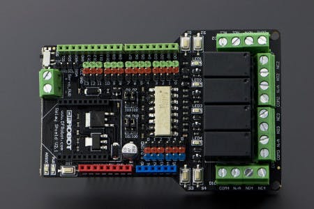

- Compatible with Arduino UNO Rev3
- 4 buttons to test module
- LED status indicator of relay
- Support Xbee IO directly control
- Xbee socket for wireless communication
- Selectable digital IO pin for control(Default digital 2,7,8,10)
- 6 channels Analog IO & 13 channels Digital IO
- Up to 4 Relay with photo-coupled circuit
- Contact Rating : 3A AC 120V / DC 24V
- Max Switching Voltage : AC 240V / DC 60V (Less than 38V is recommended)
- Max Switching Current : 5A
- Max Switching Power : AC 360VA / DC 90W
- Electrical Life (Min) : 100,000 Operations
- Mechanical Life (Min) : 10,000,000 Operations
- Safety Standard(relay) UL cUL TUV CQC
- Coil Working Voltage 9VDC
- Working temperature -30℃ to +85℃
- Working Humidity 40% - 85>#/li###
- Size: 95x65mm
IR Kit for Arduino


The Working
High Voltage VS Low Voltage
We all know that the appliances work on 110 V (USA) and 220 V (Asia)depending upon the region. But, the Arduino we are using is working on just 5 V. If we connect it directly to the mains supply to control the appliances just like controlling the LEDs, the board or the microcontroller will get burned. So, we use 5 V relay which works as an interface between the two voltage supplies. A signal is sent to relay by Arduino and relay switches on the circuit of the appliance.
Wireless Transmission of Data
We know that how will we switch the supply on but we need to send the signal from an IR remote to the receiver with Arduino. So, we can use any generic IR remote controller available in market. But, every remote controller comes with different codes for their buttons which they send it through IR LED. So, we need to find those codes for a random IR remote controller we are using.
For that, please click here for another project of mine on Hackster.io.
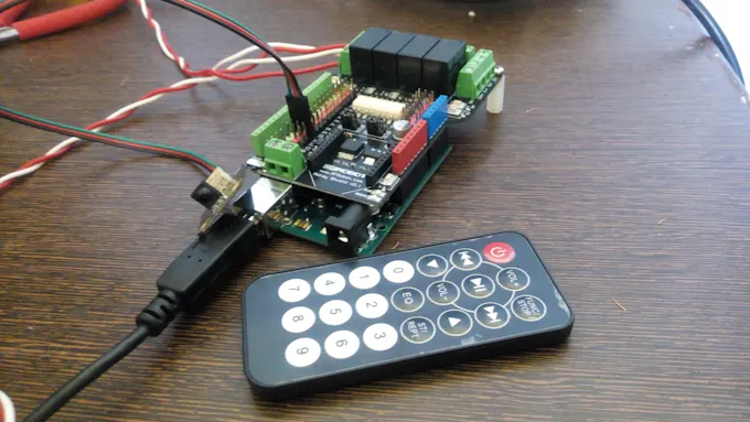
Hook-up the Circuit
IR receiver and relay connections:
- Just stack the relay shield on the Arduino board.
- On the shield, there are male headers for digital I/O pins.
- Connect the connector cable for IR module in the PIN 11 of the board. Keep in mind the colors on the wires matching with each other.
Testing it up!
Remember to install the IRremote.h library in the Arduino IDE. Download the ZIP File.
- Upload the code attached in the end of project.
- Wait for the system to initialize.
- Now, press the POWER button to switch ON/OFF all the appliances.
- Press each corresponding button (like 1 for fan, 2 for light and so on) to switch ON/OFF them.

Try this and let me know in the comment section of your face any problem in the project I have published.
 Jithin Sanal
 Subhajit
 Dixon Selvan