0%
0%
The PCW Project
Doing things with an Amstrad PCW
 James Ots
Become a Hackaday.io member
Already have an account? Log in.
Just one more thing
To make the experience fit your profile, pick a username and tell us what interests you.
Pick an awesome username
hackaday.io/
Your profile's URL: hackaday.io/username. Max 25 alphanumeric characters.
Pick a few interests
Projects that share your interests
People that share your interests


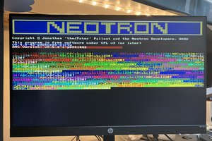
 Jonathan 'theJPster' Pallant
This project is invaluable to me as I have a PCW in bits and I'm looking to do something with it. I took it apart to re-cap it but am now looking to expand it with a similar system as this one. Thank you for doing all this work - it's of historical interest, as well as being a way to use the PCW far beyond its intended lifespan.