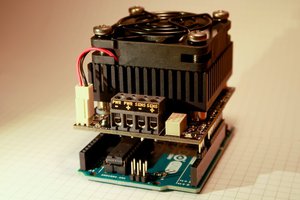
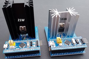
Arduino compatible Electronic Load 19V 5A 16W or 21W
This the second revision of my electronic load. It is intended for testing DC power supplies, solar panels and battery capacity. The load can be easily set using the Arduino Serial Monitor.
It is special because the hardware and software is open source, it is Arduino compatible, and it is a cheap tool all hardware designers should have. The software is made by my brother Bertrik. With respect to revision 1 the Arduino Nano was upgraded to a STM32 Arduino compatible board and as a result, the resolution to measure voltage and current has improved much (12 bit in stead of 10 bit ADC). It works up to 19.8V, 5A and 18W/31W. The load can be set to constant current, constant power, or constant resistance by simply typing it into the Arduino Serial monitor. The constant current loop is implemented in hardware with an opamp, a mosfet, and a small current sense resistor. For setting the current a 16-bits timer is used to generate a PWM signal, that is low pas filtered to make it an analog input signal for the constant current circuit. The constant power and constant resistance mode is implemented in software. Load voltage and current are measured using a pair of high precision opamps (MCP6074) and the STM32 12-bits ADC. Battery capacity is measured by loading the battery with constant current and integrating current over time. To protect the battery against undervoltage the load is removed when the voltage falls below a configurable threshold. The device can also be used to simply log a voltage or current over time.
Specifications
- Current set range: 0 to 5A
- Current set resolution: 10-bit, 4.88 mA/bit
- Current set accuracy : 5% in range 0.1 to 5A
- Current read range: 0 to 5A
- Current read resolution: 12-bit, 1.22 mA/bit
- Current read accuracy : 5% in range 0.1 to 5A
- Voltage read range : 0 to 19.8V
- Voltage read resolution: 12-bit, 4.83 mV/bit
- Voltage read accuracy: 5% in the range 0.15 to 19.8V
- Power dissipation: 18W (standard heat sink) or 31W (extra large heat sink) by natural convection
- MOSFET: BTS133. It has ESD, thermal, overvoltage, overcurrent, and overload protection!
- Microcontroller: STM32F103C8T6 ARM Cortex-M3 (blue pill)
- Power supply: micro USB cable (not included)
- Load connector: 2 pins screw terminal 5.08mm pitch 24-12 AWG, and 4 mm PCB holes for banana plugs
- Net Weight: 80 grams
- Size: 79x53x49mm standard 16W heat sink, 79x53x67mm extra large 21W heat sink
- USB cable is not included
Quik start
- Connect your power source to the plus and minus terminal of electronic load
- Connect USB cable to the computer
- Start Arduino IDE
- Select the COM port (both NL & CR, 115200 bps)
- Open Arduino Serial Monitor
- Type any of the commands below into Serial Monitor
- Every second the voltage, current, power and mAh are printed to the serial port
Serial Monitor Commands
- Type CC 100 to set a constant current of 100 mA
- Type CP 100 to set a constant power of 100 mW
- Type CR 100 to set a constant resistance of 100 Ohm
- Type limit v 1000 to set the undervoltage limit to 1000mV
- Type limit p 15000 to set the power limit to 15W
- Type help for more commands
Storing the data
Arduino Serial Monitor is not able to store the serial port data. I recommend using Realterm because it can store the data in a file and add a timestamp for further processing in other tools, for example in a spreadsheet.
Testing a power supply
Constant voltage power supplies can be tested by applying different loads and see how the voltage is affected. It may also be used to test a dc-dc converter efficiency under different loads. For example type cc 100 in the serial monitor and you will see the the current being set and the voltage updating at regular interval. Soon pulsed loads will be supported in embedded code.
Testing a solar panel
Solar panels...
Read more » Jasper Sikken


 Alex Fatiuk
 CentyLab
I've received mine a couple months ago, and found it very useful.
I 'hacked' it by using some of the unused pins of the STM32 to drive a small I2C OLED display and some buttons (through an MCP23017). That way, I can use it even without a controlling computer attached. I also added an I2C EEPROM (24LC256) to allow storing measured values.
Great device for sure!