 CentyLab
-
Variable power supply with USB-C PPS - PicoPD
09/20/2023 at 06:04 • 0 commentsThis article is beginner-friendly. If you have some experience, you can skip to the wiring and the code.
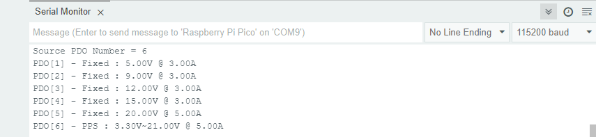
I made the PicoPD a while back to combine the AP33772 IC along with our lovely RP2040 microcontroller. One of the capabilities of the IC is taping the Programmable Power Supply (PPS) of compatible USB-C brick. I would recommend anyone to get UGREEN 140W if you also own a higher power MacBook Pro that can quickly charge at 140W at 28V and 5A. Let me know in the comment if you also recommend other 140W chargers. First, let's take a look at the power capability of the power brick using the AP33772-Cpp library:
![]()
As you can see at PDO[6], the charger has the ability to supply power ranging from 3.3V to 21V at a maximum current of 5A. This seems to be exactly what we need to make a constant voltage power supply.
Game plan
Constant voltage mode: Straight forward, just request the desired voltage from the charger. Might need to set the current limit at the max. The USB-C charger tends to give you a bit more voltage than you are asking for as it is trying to compensate for the voltage drop across the cable.
Constant current mode:
- Most complex: Reading the current through the AP33772, and making a micro adjustment to the voltage in the 20mV step. This would work like a PID control loop. Difficulty: we don't know the response speed of the USB-C charger after each request
- Less complex: Another possibility is the power supply has built-in constant current mode and we just need to set the MaxCurrent in the code.
- Simpliest: Monitor the current and turn off the output if exceeds a certain threshold.
Components
- 1x PicoPD = 1x AP33772 Evaluation board + RP2040
- Alternative: Raspberry Pi Pico + AP33772 Eval (USB-C Sink 2 Click) + 20V to 5V LDO (power for Pi Pico)
- 1x UGREEN 140W Charger
- 2x potentiometers (10k to 20K)
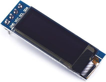
- 1x OLED Screen 128x32 - SSD1306
Connection
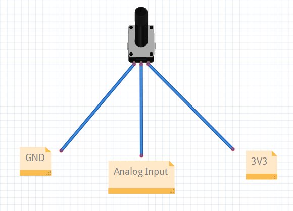
The wiring is extremely simple since we only need to connect 2 potentiometers and one OLED screen. Here is the wiring needed for each:
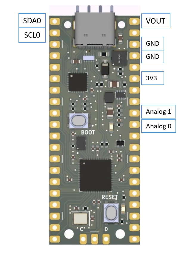
- Pot1: GND, Analog Input1 , 3V3
- Pot2: GND, Analog Input2, 3V3
- OLED: SDA0, SCL0, 3V3 and GND
Not all OLED module has an I2C pull-up resistor. If you are using PicoPD, the Pin 0 (SDA0), and Pin 1 (SCL0) already have two 5.1K pull-up resistors. Otherwise, remember to add a 4.7k to 10k pull-up resistor between SDA to 3V3 and SCL to 3V3.
![]()
![]()
![]()
The Code
For the main program, we will be using libraries:
- Pico-core: Earle F. Philhower
- jrullan/Neotimer@^1.1.6
- adafruit/Adafruit SSD1306@^2.5.7
- robtillaart/RunningAverage@^0.4.3
- centylab/AP33772-Cpp
This code sets both voltage and current limits on the charger. There is no feedback loop at the microcontroller end. So we are just hoping the charger has the current capability. Writing up to this point, I should also design another failsafe method if the charger doesn't have current limit ability. But how do I even check if the charger can do that?
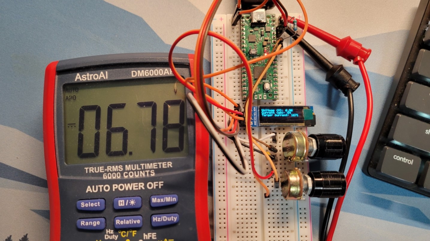
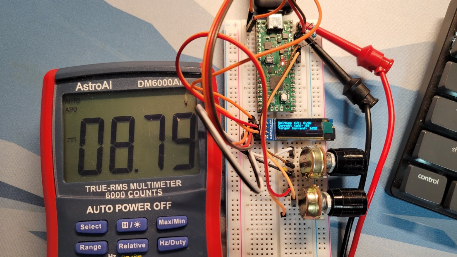
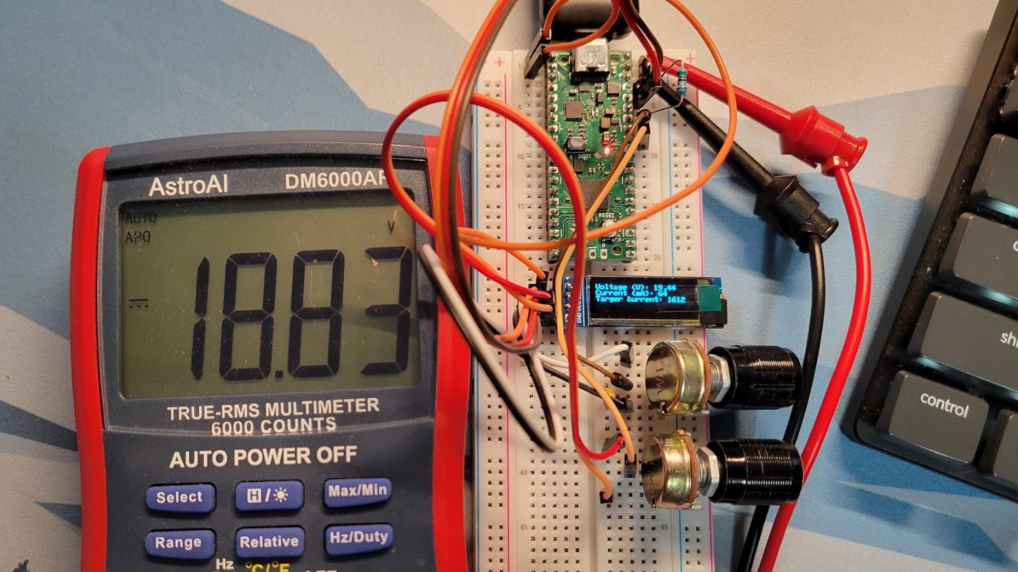
Up to this point, I have successfully set the desired voltage via the potentiometer. However, if you look at the result pictures, there is always a slight offset between what the AP33772 is reporting and what my DMM is reading. As of right now, there is almost no load on the supply besides the RP2040 and power LED. Once I can get some 5W load from Amazon, I will be able to verify:
- The actual current reading
- The actual voltage when loaded
- If my USB-C charger has a current limiting feature
Find the current project code at GitLab - PicoPDSupply. If you want to use Arduino IDE, make sure you install the Earle F. Philhower Pico Core and the rest of the library mentioned above.
Result
Using the UGREEN 140W Charger
![]()
![]()
![]()
This user joined on 08/03/2023.
 sjm4306
 eBender
 anfroholic
 oshpark
 sky-guided
 Flip Schaumal
 William Somsky
 Cary W.
 muzi
muzi Juan Flores
 Spectre
 Alex Fatiuk
 Andrzej Strzała
 mit41301